00195982-03_SM_SWS_EN.pdf - 第76页
5 Basic frame – X/Y unit 5.3 Replacing parts 76 Service Manual SIPLACE Wafer System (SWS) 11/2018 Fig.57: ► Remove the clamping screw for the coupling shown in the diagram! Fig.58: ► Carefully pull the whole coupling p…
5 Basic frame – X/Y unit
5.3 Replacing parts
Service Manual SIPLACE Wafer System (SWS) 11/2018 75
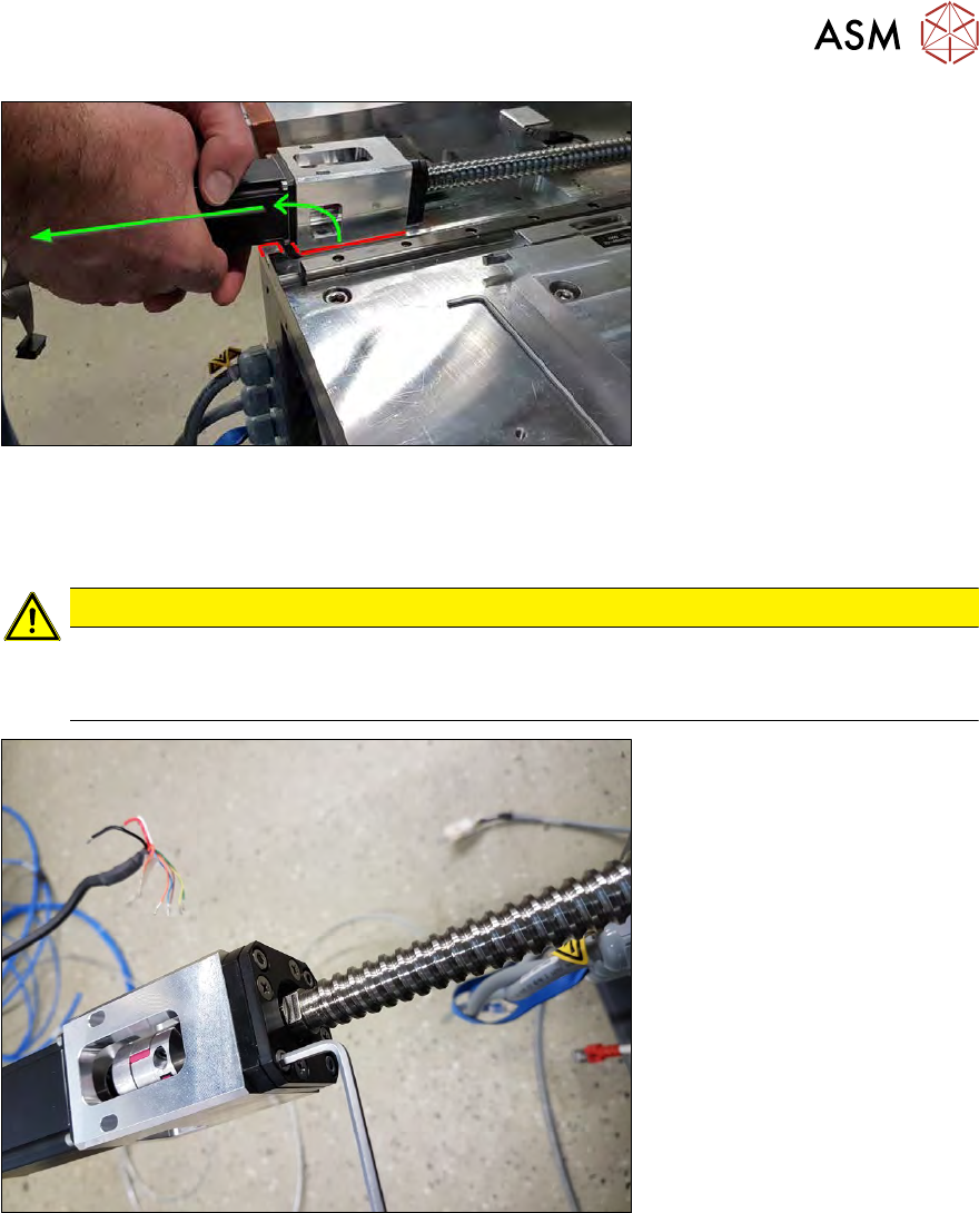
Fig.55:
► Pull the complete spindle backwards on the Y motor.
Carefully lift the motor slightly, so that the underside of the coupling plate can be moved over
the edge of the base plate.
CAUTION
The wafer table must be in the rearmost position (at the magazine lift), so that there is as
little bending inflicted on the spindle as possible when the motor is lifted.
► Take the greatest care whenever you are lifting.
Fig.56:
► Remove the four Allen key fastening screws (not the Phillips screws) from the coupling plate.
5 Basic frame – X/Y unit
5.3 Replacing parts
76 Service Manual SIPLACE Wafer System (SWS) 11/2018
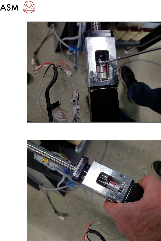
Fig.57:
► Remove the clamping screw for the coupling shown in the diagram!
Fig.58:
► Carefully pull the whole coupling plate-motor-coupling unit off the spindle.
5 Basic frame – X/Y unit
5.3 Replacing parts
Service Manual SIPLACE Wafer System (SWS) 11/2018 77
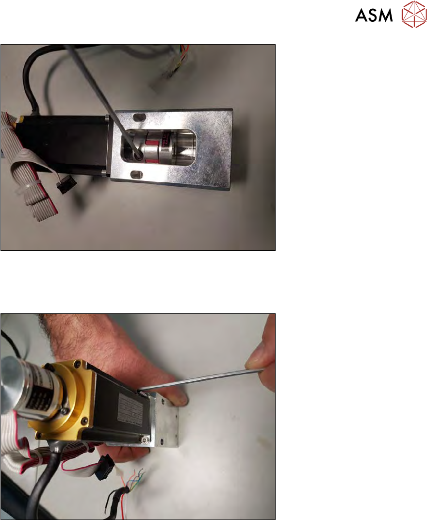
Fig.59:
► Remove the coupling clamping screw for the motor shaft.
You might need to widen the coupling clamp with a screwdriver.
► Pull the coupling off the motor shaft.
Fig.60:
► Remove the four screws fastening the motor to the coupling plate.