00195982-03_SM_SWS_EN.pdf - 第70页
5 Basic frame – X/Y unit 5.2 Complete overview 70 Service Manual SIPLACE Wafer System (SWS) 11/2018 5.2.3 Overview of sensors Fig.47: Fig.48:
5 Basic frame – X/Y unit
5.2 Complete overview
Service Manual SIPLACE Wafer System (SWS) 11/2018 69
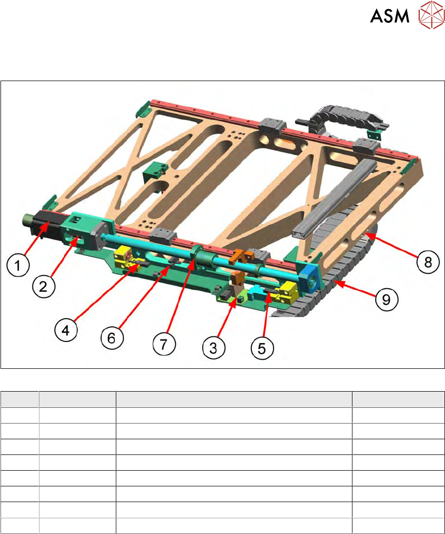
5.2.2 X/Y unit – design and spare parts [00386776-xx] (example SWS 1/3)
This unit is responsible for movement of the wafer table in the X direction.
Fig.46:
Item Item no. Designation Comments
1 00385072-xx Brushless cybermotor - X axis
2 03106447-xx Elastomer coupling without play d6,d10
3 0384600-xx AD-MOT Rev.0 Sub-D board = angled Under the cover
4 Ball screw drive and bearing unit
5 0386343-xx Proximity switch, inductive, PNP/1OE RL2
6 0386343-xx Proximity switch, inductive, PNP/1OE FL2
7 00379046-xx Adapter board wafer table AD-WT Rev.0 Under the cover
8 Cover shield for heating unit (stretcher) --> option
The spare parts for the
X/Y unit SWS12 (1,3) - [00386776-xx]
and the
X/Y unit SWS12 (2,4) - [00385864-xx]
are identical.
5 Basic frame – X/Y unit
5.2 Complete overview
70 Service Manual SIPLACE Wafer System (SWS) 11/2018
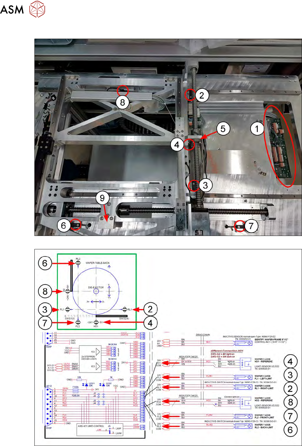
5.2.3 Overview of sensors
Fig.47:
Fig.48:
5 Basic frame – X/Y unit
5.2 Complete overview
Service Manual SIPLACE Wafer System (SWS) 11/2018 71
Item Item no. Designation Comments
1 00379046-xx Adapter board wafer table AD-WT Rev.0
2 00386343-xx Proximity switch, inductive, PNP/1OE RL1
3 00386343-xx Proximity switch, inductive, PNP/1OE FL1
4 00384820-xx Fork light barrier (home sensor X axis) HO1
5 Actuator for proximity switch X axis
6 00386343-xx Proximity switch, inductive, PNP/1OE RL2
7 00386343-xx Proximity switch, inductive, PNP/1OE FL2
8 00384820-xx Fork light barrier (home sensor Y axis) HO2
9 Actuator for proximity switch Y axis
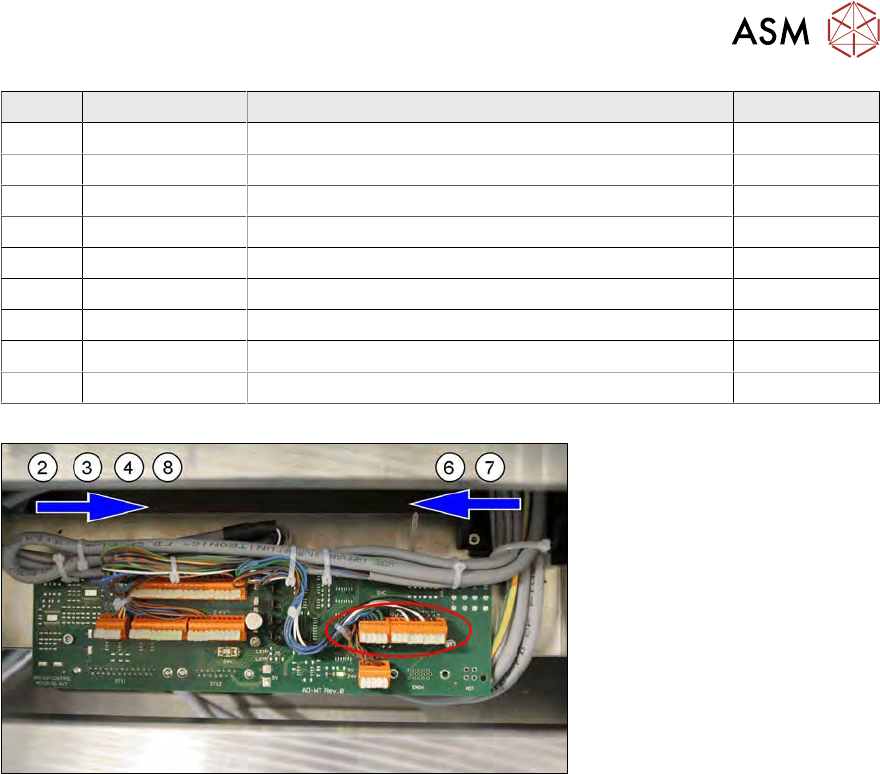
The sensors run together on the wafer table adapter board AD-WT REv.0 [00379046-xx].
Fig.49:
The proximity switches RL1 and FL1 and the two home sensors HO1 and HO2 come from one side
(from the left in the example SWS 2/4).
The proximity switches RL2 and FL come from one side (from the right in the example SWS 2/4).
The sensor cables run under the thick base plate.
The sensor cables are connected as follows: