00195982-03_SM_SWS_EN.pdf - 第159页
7 Die ejector 7.5 Mechanical adjustment of the die ejector unit in the Z direction (focus) Service Manual SIPLACE Wafer System (SWS) 11/2018 159 7.5.1.3 Setting the needles with the calibration standard [03080191-xx] Too…
7 Die ejector
7.5 Mechanical adjustment of the die ejector unit in the Z direction (focus)
158 Service Manual SIPLACE Wafer System (SWS) 11/2018
7.5.1.2 Setting the needles with the calibration standard [03098221-xx] (for die ejector,
magnetic)
Tools
●
Needles (wear part)
●
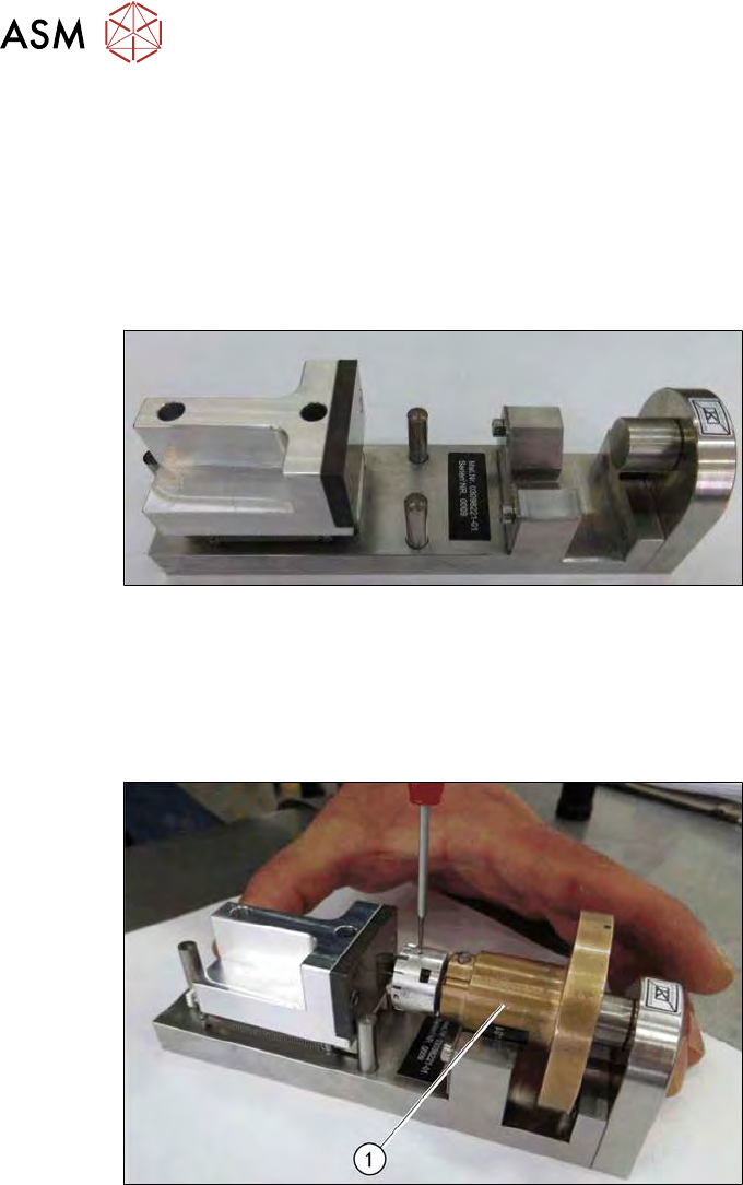
Calibration standard for die ejector, magnetic [03098221-xx]
The needles are all set at a defined height and common level with the help of the calibration
standard for the die ejector.
Fig.201: Calibration standard for die ejector, magnetic [03098221-xx]
Procedure
► Remove the black cap on the needle unit.
► Carefully insert all needles into the segments and align the needles roughly in one line.
► Loosely tighten the grub screws. You must still be able to move the needles.
Fig.202: Calibration standard for die ejector, magnetic
► Place the needle unit into the calibration standard for the die ejector (1).
► Place the ejection part into the device. The central bolt of this device must be against the ejec-
tion plunger and the bronze part must be flexibly against the radius nib.
► Turn the ejection part (bronze) into the required position.
► Press the bronze part slightly down into the prisms of the device.
► Push the ejection needles into the required holes (the threaded pin must be released).
► Move the spring-back adjusting slide in the direction of the stop bolt and hold it in place.
► Push the ejection needles in the direction of the setting surface (use tweezers) and pull the
ejection needle tightly into place with the threaded pins (torque 0.1Nm).
7 Die ejector
7.5 Mechanical adjustment of the die ejector unit in the Z direction (focus)
Service Manual SIPLACE Wafer System (SWS) 11/2018 159
7.5.1.3 Setting the needles with the calibration standard [03080191-xx]
Tools
●
Needles as wear part
●
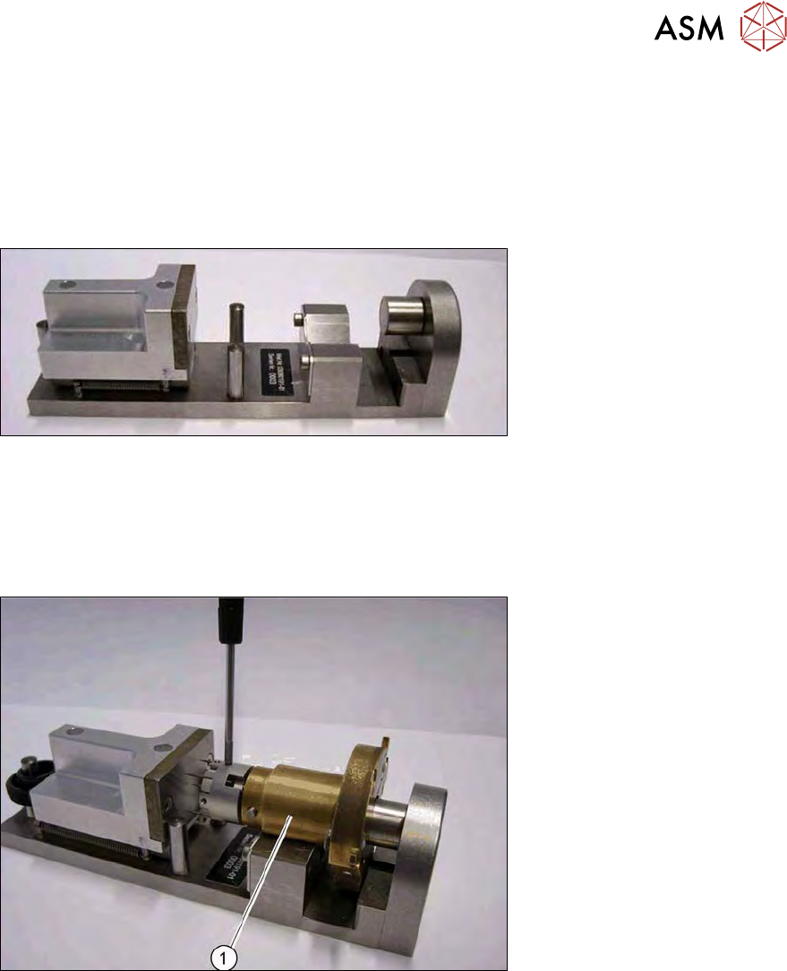
Calibration standard for die ejector with bayonet fastening [03080191-xx]
The needles are all set at a defined height and common level with the help of the calibration
standard for the die ejector.
Fig.203: Calibration standard for die ejector with bayonet fastening [03080191-xx]
Procedure
► Remove the black cap on the needle unit.
► Carefully insert all needles into the segments and align the needles roughly in one line.
► Loosely tighten the grub screws. You must still be able to move the needles.
Fig.204: Calibration standard for die ejector
► Place the needle unit into the calibration standard for the die ejector (1).
► Place the ejection part into the device. The central bolt of this device must be against the ejec-
tion plunger and the bronze part must be flexibly against the radius nib.
► Turn the ejection part (bronze) into the required position.
► Press the bronze part slightly down into the prisms of the device.
► Push the ejection needles into the required holes (the threaded pin must be released).
► Move the spring-back adjusting slide in the direction of the stop bolt and hold it in place.
► Push the ejection needles in the direction of the setting surface (use tweezers) and pull the
ejection needle tightly into place with the threaded pins (torque 10Nm).
7 Die ejector
7.5 Mechanical adjustment of the die ejector unit in the Z direction (focus)
160 Service Manual SIPLACE Wafer System (SWS) 11/2018
7.5.1.4 Checking the needle ejection unit for air-tightness
► In the toolbar, select the button Service Settings => Main vacuum control system (see
14.1 "SWS GUI - service settings" [}357]).
► The Main vacuum should be between 740 and 840 mbar.
► Place a piece of foil onto the ejection system, so that all openings are closed.
► Now switch on the vacuum at the die ejector.
► Enable Vacuum valve ejection unit opened.
ð Suction will be applied to the foil by the ejection system.
ð The Main vacuum should reach the value previously shown, if possible (i.e. no losses).
Troubleshooting in the event of leakages
► Switch the vacuum on at the die ejector (software) and check the suction force at the sealing
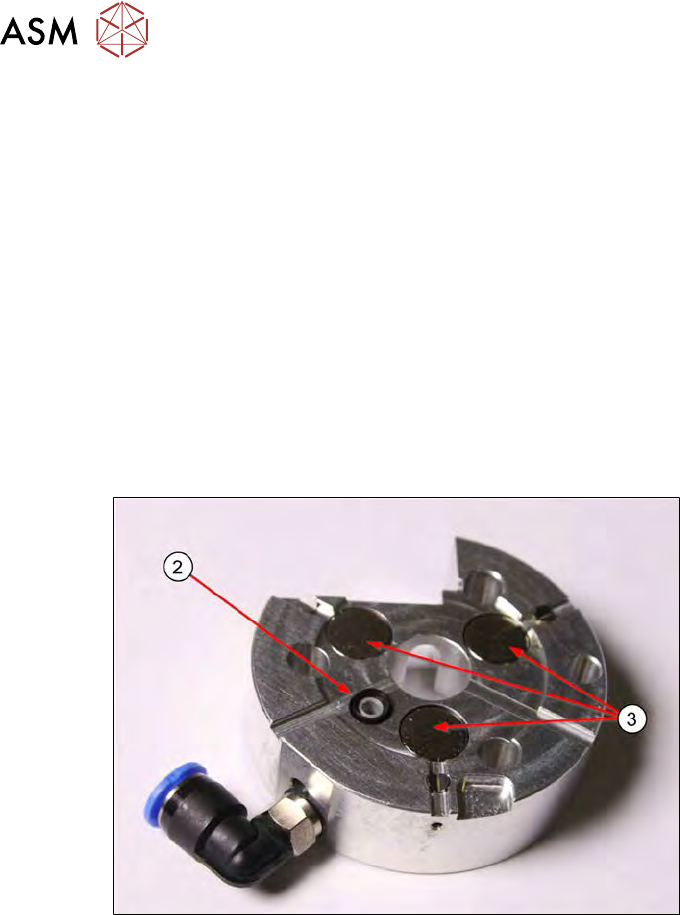
lip with your finger(2).
► Check whether the vacuum inlet cable is free of bends/folds.
Fig.205:
► Perform a sight check of the sealing lip (2) for possible damage and replace, if necessary (see
7.5.1.5 "Replacing the sealing unit and the O-ring on the die ejector centering unit" [}162]).
► Check the magnets (3) for foreign bodies.