00195982-03_SM_SWS_EN.pdf - 第26页
2 Overview of the SIPLACE wafer system (SWS) 2.3 Detailed overview of main assemblies 26 Service Manual SIPLACE Wafer System (SWS) 11/2018 2.3.1 Overview of assemblies in wafer table area Fig.7: Overview of assemblies f…
2 Overview of the SIPLACE wafer system (SWS)
2.3 Detailed overview of main assemblies
Service Manual SIPLACE Wafer System (SWS) 11/2018 25
2.3 Detailed overview of main assemblies
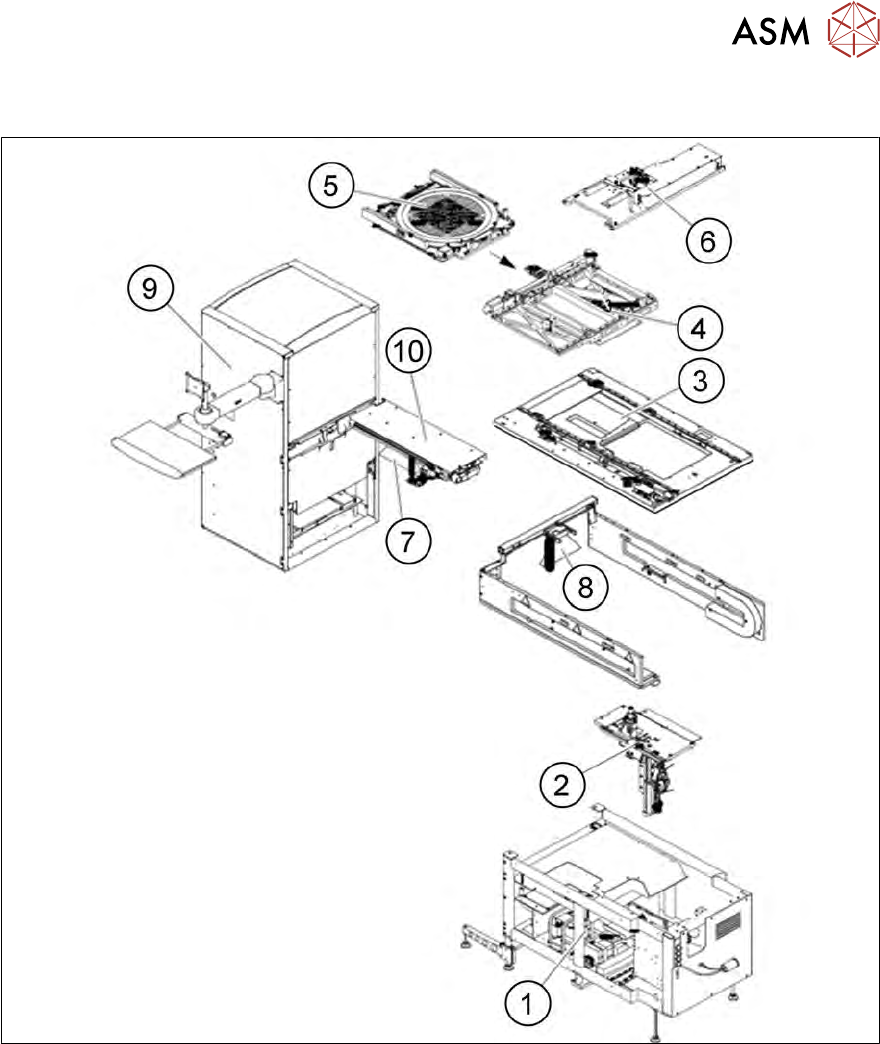
Fig.6: Exploded view of main assemblies
1 Supply unit 2 Die ejector
3 Basic frame 4 X/Y unit
5 Wafer support for 8" or 12", fitted to X/Y
unit
6 Flip unit
7 Barcode scanner fitted to side of gripper
or (8) barcode scanner fitted to side of
magazine lift
8 Barcode scanner fitted to side of
magazine lift
9 Wafer-magazine lift 10 Wafer-changer unit
2 Overview of the SIPLACE wafer system (SWS)
2.3 Detailed overview of main assemblies
26 Service Manual SIPLACE Wafer System (SWS) 11/2018
2.3.1 Overview of assemblies in wafer table area
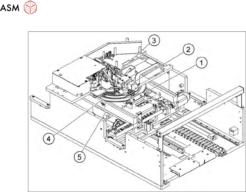
Fig.7: Overview of assemblies for SWS
1. Clamping unit
2. Wafer camera
3. Flip unit
4. Wafer support
5. Guidance
2 Overview of the SIPLACE wafer system (SWS)
2.4 Description of SWS assemblies
Service Manual SIPLACE Wafer System (SWS) 11/2018 27
2.4 Description of SWS assemblies
2.4.1 Supply unit
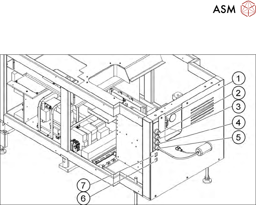
Fig.8: Supply unit
1. Manometer for compressed air supply
2. Power supply
3. Communication with the placement machine
4. CAN bus
5. Compressed air connection (modified adapter dummy plug [03011592‑xx]
6. LAN1
7. LAN2