00195982-03_SM_SWS_EN.pdf - 第79页
5 Basic frame – X/Y unit 5.3 Replacing parts Service Manual SIPLACE Wafer System (SWS) 11/2018 79 5.3.1.2 Removing the Y motor (alternative, without coupling) Special tool ● T Allen key 2.5mm (not contained in the stand…
5 Basic frame – X/Y unit
5.3 Replacing parts
78 Service Manual SIPLACE Wafer System (SWS) 11/2018
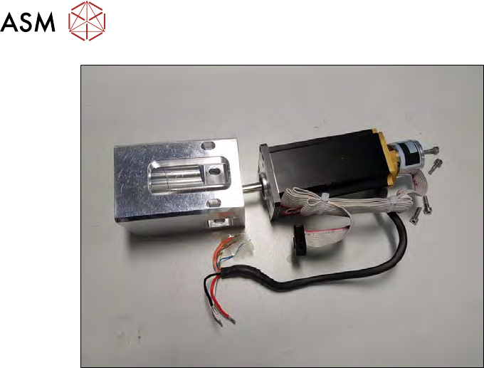
Fig.61:
The Y motor and coupling plate are now separate.
Pay attention to the position.
5 Basic frame – X/Y unit
5.3 Replacing parts
Service Manual SIPLACE Wafer System (SWS) 11/2018 79
5.3.1.2 Removing the Y motor (alternative, without coupling)
Special tool
●
T Allen key 2.5mm (not contained in the standard set of tools)
Procedure
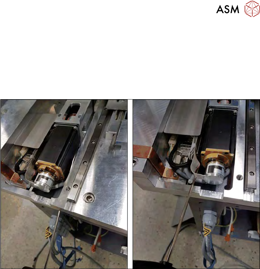
The motor can, in certain circumstances, be replaced more easily. To do so, proceed as follows:
► Unplug the cable connections from the adapter board.
► Remove the coupling clamping screw for the motor shaft.
Fig.62:
► Take a long T Allen key and open the four screws fastening the motor on the coupling plate!
The access to the two lower screws could vary (e.g. underneath the base plate).
► Remove the motor!
5 Basic frame – X/Y unit
5.3 Replacing parts
80 Service Manual SIPLACE Wafer System (SWS) 11/2018
5.3.1.3 Fitting the Y motor and coupling
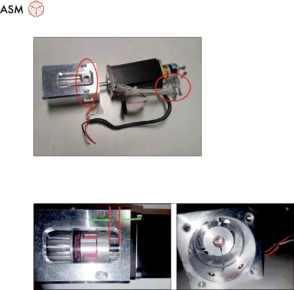
Fig.63:
► Fit the new Y motor.
► Pay attention to the alignment of the motor cable to the assembly holes on the coupling plate
(see diagram).
► Tighten the four fastening screws. Secure the screws with Loctite 243.
Fig.64:
► Place the new coupling (alignment as in diagram - label facing away from motor) with a dis-
tance of approx. 4 mm to the cut-out edge.
► The motor shaft should not project into the elastomer of the coupling (see diagram on the
right).
► Slightly tighten the coupling clamping screw on the motor shaft.