00195982-03_SM_SWS_EN.pdf - 第137页
7 Die ejector 7.3 Replacing spare parts Service Manual SIPLACE Wafer System (SWS) 11/2018 137 Fig.163: Fig.164: ► Fit the board cover.
7 Die ejector
7.3 Replacing spare parts
136 Service Manual SIPLACE Wafer System (SWS) 11/2018
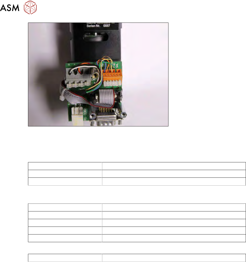
Fig.162:
► Connect all cables (small screwdriver).
► Connect the encoder signal (ENC).
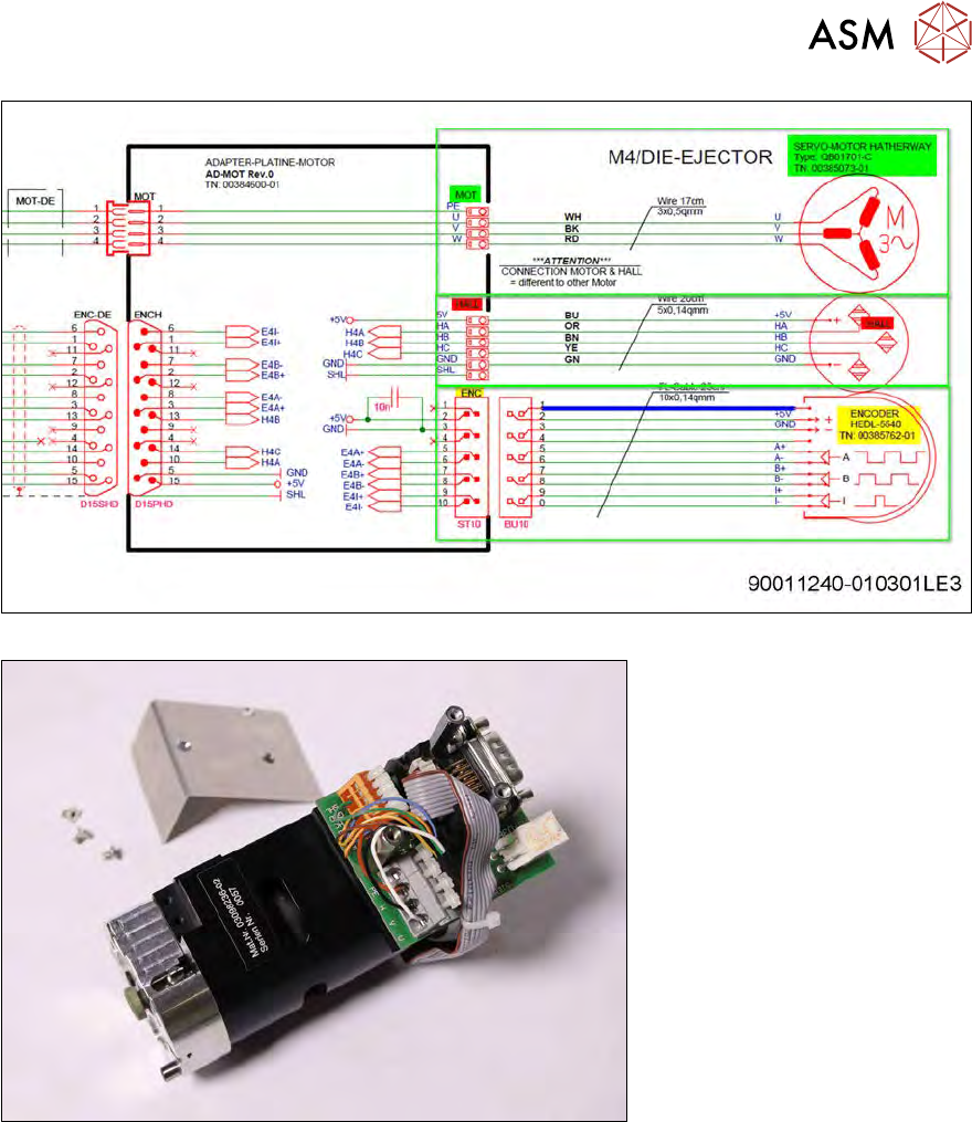
Wiring overview for motor connection
Cable, white (WH) U
Cable, black (BK) V
Cable, red (RD) W
Wiring overview of Hall sensor connection (detection of rotary position for direction
of movement)
Cable, blue (BU) +5 V
Cable, orange (OR) HA
Cable, brown (BN) HB
Cable, yellow (YE) HC
Cable, green (GN) GND
Wiring overview for encoder signal
Gray flat ribbon cable BU10-ST10 ENCO
7 Die ejector
7.3 Replacing spare parts
Service Manual SIPLACE Wafer System (SWS) 11/2018 137
Fig.163:
Fig.164:
► Fit the board cover.
7 Die ejector
7.3 Replacing spare parts
138 Service Manual SIPLACE Wafer System (SWS) 11/2018
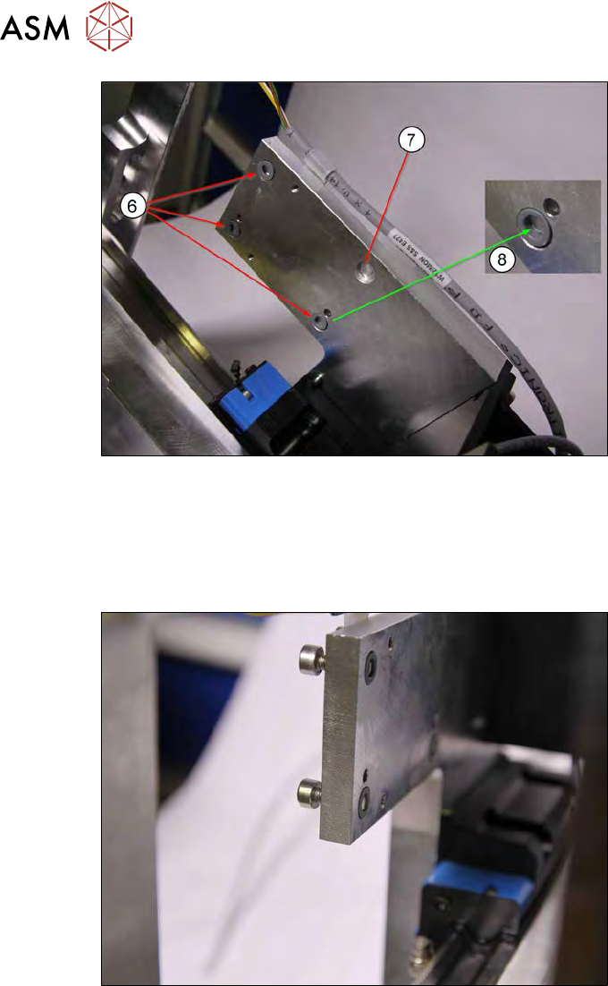
Fig.165:
► All loss prevention locks [03075495-xx](6) must be in the Flachbohrungen.
In order to fix the loss prevention locks into place, you can apply a little Vaseline or similar
grease to the shallow holes(7).
► The thread of the loss prevention locks must be on the inside (towards the shallow hole)(8).
This is the only way to ensure that the screws have approx. 2mm secure hold.
Fig.166:
It is possible that the screws may still be in the loss prevention lock after dismantling.
► Tighten all screws so that they are level with the assembly surface (see diagram).