00195982-03_SM_SWS_EN.pdf - 第33页
2 Overview of the SIPLACE wafer system (SWS) 2.4 Description of SWS assemblies Service Manual SIPLACE Wafer System (SWS) 11/2018 33 2.4.1.4 Die ejector According to the location (2/4 or 1/3) there are two different varia…
2 Overview of the SIPLACE wafer system (SWS)
2.4 Description of SWS assemblies
32 Service Manual SIPLACE Wafer System (SWS) 11/2018
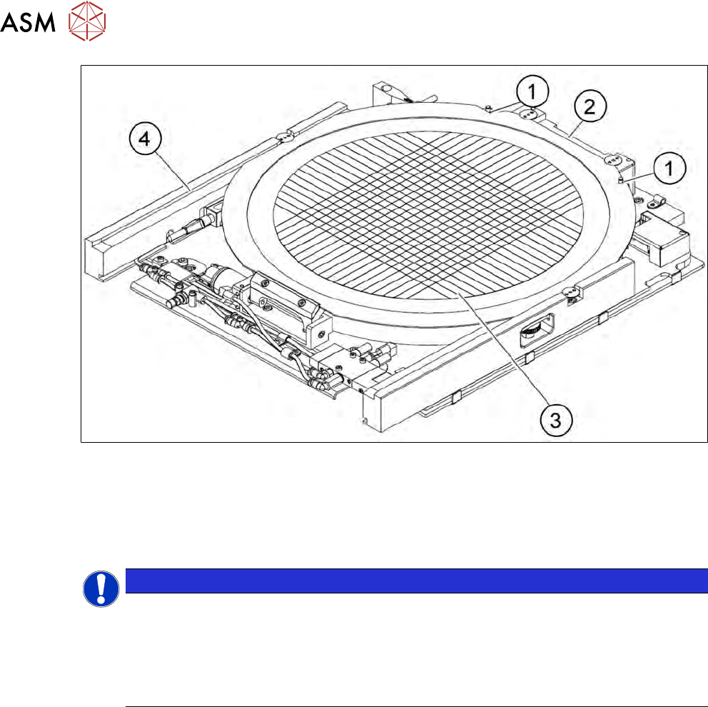
Fig.13: Wafer support with wafer inserted (example for 12")
1. Recess for the defined positioning on the pins of the locking strip
2. Wafer locking strip
3. Wafer
4. Rail
NOTICE
Problems recognizing frames during clamping
If the wafer locking strip (2) has been incorrectly attached, the frame will not be recognized
correctly during clamping.
► When using 8" wafer supports, observe the following: make sure that the wafer locking
strip (2) is attached in a manner that allows the pins of the locking strip to engage with
the recess on the wafer frame.
2 Overview of the SIPLACE wafer system (SWS)
2.4 Description of SWS assemblies
Service Manual SIPLACE Wafer System (SWS) 11/2018 33
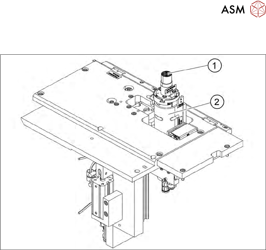
2.4.1.4 Die ejector
According to the location (2/4 or 1/3) there are two different variants that only differ in their mirrored
arrangement of the modules.
Fig.14: Main die ejector assemblies
1. Ejector tool
2. Z axis
2 Overview of the SIPLACE wafer system (SWS)
2.4 Description of SWS assemblies
34 Service Manual SIPLACE Wafer System (SWS) 11/2018
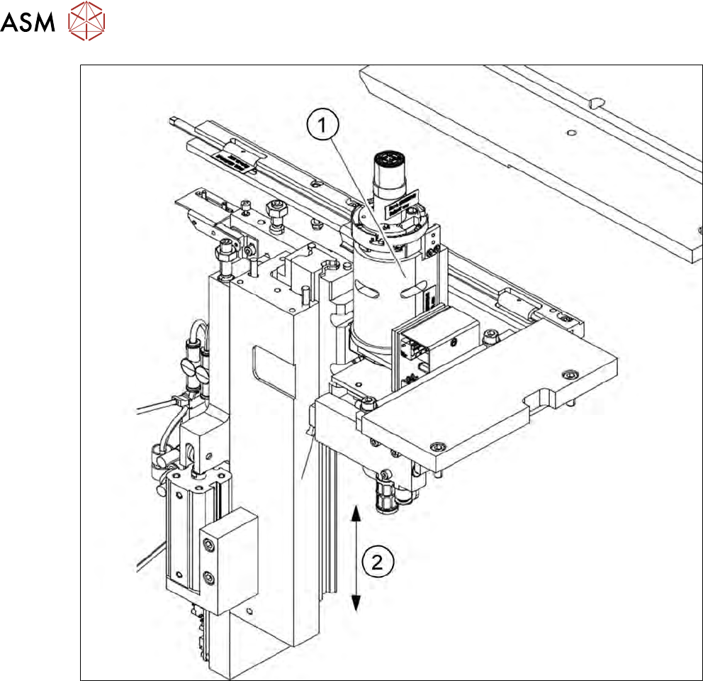
Fig.15: Die ejector basic unit
1. Z axis
2. Z axis movement (pneumatic)