00195982-03_SM_SWS_EN.pdf - 第271页
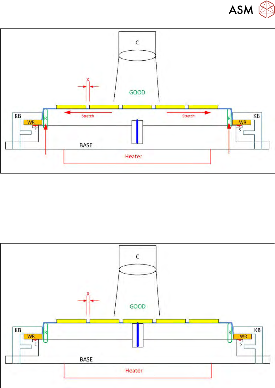
12 Wafer stretcher 12.2 Detailed description of "wafer stretching" procedure Service Manual SIPLACE Wafer System (SWS) 11/2018 271 Fig.369: ● The clamping ring (R) is now moved upwards. ● This "stretches&…
12 Wafer stretcher
12.2 Detailed description of "wafer stretching" procedure
270 Service Manual SIPLACE Wafer System (SWS) 11/2018
12.2 Detailed description of "wafer stretching" procedure
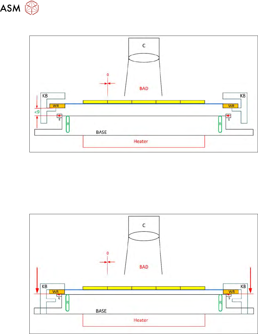
Fig.367:
●
The wafer frame (WR) is positioned on the support strip of the clamping plate (KB).
●
The base (BASE) with the clamping ring (R) and the heating (heater) has a spacing of more
than 9mm!
●
The camera (C) is unable to clearly recognize a single die (BAD), as the distance between
dies is nearly 0.
●
This makes is impossible to guarantee reliable pickup and ejection due to the friction between
the die edges.
Fig.368:
●
The wafer frame (WR) is now moved downwards until it is on the surface of the base (BASE).
●
The downwards movement of the clamping plate (KB) means that the wafer frame (WR) is no
longer on the support strip of the clamping plate but is instead pressed against the surface of
the basic unit (BASE) by the underside of the clamping plate, in other words, it is clamped!
12 Wafer stretcher
12.2 Detailed description of "wafer stretching" procedure
Service Manual SIPLACE Wafer System (SWS) 11/2018 271
Fig.369:
●
The clamping ring (R) is now moved upwards.
●
This "stretches" the wafer foil (stretch).
●
This stretching forces an expansion of the space between the dies (X).
●
The camera (C) can now clearly recognize the die (GOOD).
●
This space (X) guarantees a reliable ejection and pickup process as the dies no longer touch
and the die edges no longer rub against one another ("chipping").
Fig.370:
●
The die ejector moves upwards until the surface of the cap touches the wafer foil.
12 Wafer stretcher
12.2 Detailed description of "wafer stretching" procedure
272 Service Manual SIPLACE Wafer System (SWS) 11/2018
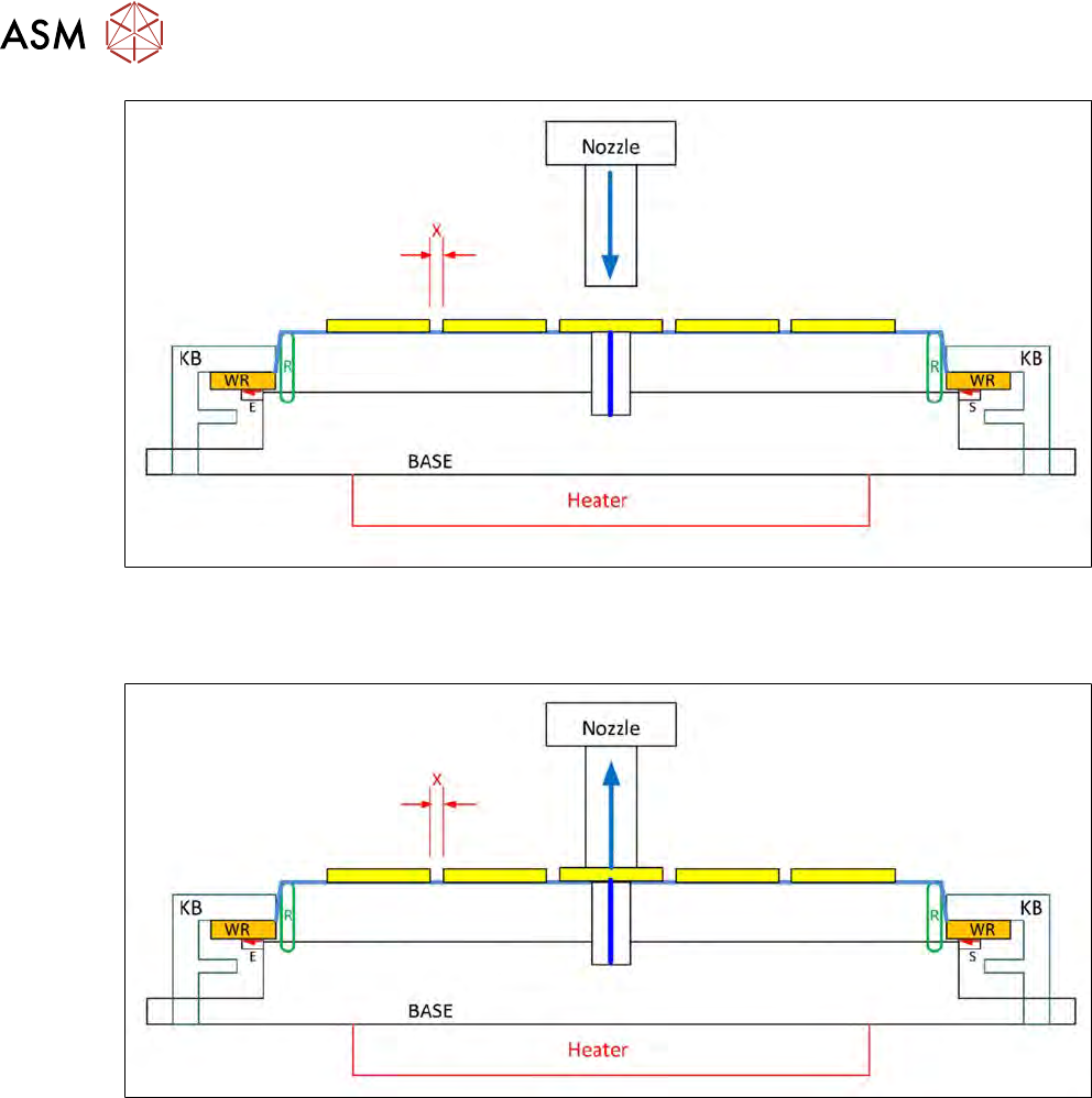
Fig.371:
●
The Z axis for the flip unit now moves downwards.
●
The camera (C) can still recognize the die clearly.
Fig.372:
●
The flip unit now moves downwards with the nozzle, until the nozzle touches the die surface.
●
The cap on the die ejector unit then also has contact with the underside of the wafer foil and
therefore to the underside of the die.