00195982-03_SM_SWS_EN.pdf - 第267页
12 Wafer stretcher 12.1 Explanation of the wafer stretcher Service Manual SIPLACE Wafer System (SWS) 11/2018 267 12.1.4 Placement accuracy and performance values Refer to the appropriate specifications. 12.1.5 Descriptio…
12 Wafer stretcher
12.1 Explanation of the wafer stretcher
266 Service Manual SIPLACE Wafer System (SWS) 11/2018
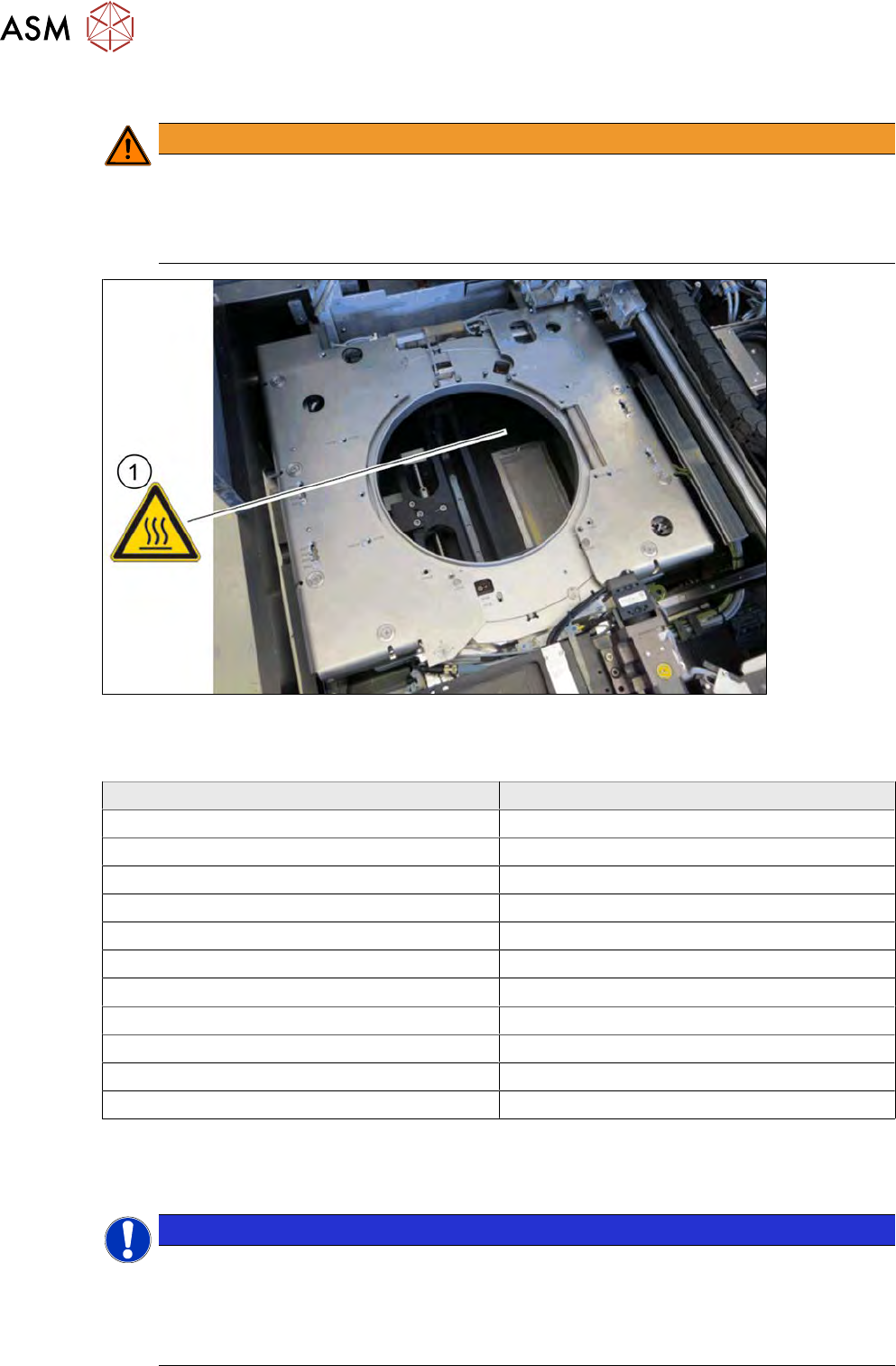
12.1.2 Safety instructions
WARNING
Risk of burns due to high temperatures!
The heating can reach temperatures of up to 60°C.
► Do not reach into the area around the fan with your hands.
► Be careful when touching the wafer support.
Fig.361: Wafer support with SIPLACE SWS wafer stretcher
12.1.3 Technical data
SIPLACE SWS wafer stretcher Value
Wafer frame 8" or 12"
Wafer width for 8" wafer frame 10.5" and 10.8"
Weight of stretcher with wafer support 8" 14kg
Weight of stretcher with wafer support 12" 15kg
Wafer frame (metal and plastic) Up to 3.5 mm thick
Minimum operating pressure 4.0bar
Maximum operating pressure 5.5bar
Travel time for full stroke Approx. 2 seconds
Lowering time Approx. 2 seconds
Stretch factor (adjustable)
1)
2 mm, 4 mm, 6 mm, 8 mm
Clamping velocity for wafer centering 0.5 to 1.0 seconds
1)
The specified stretching factors relate to a wafer frame with a thickness of 1.5 mm. The following
applies for other wafer frame thicknesses:
Stretching factor = set stretch height + frame thickness ‑ 1.5 mm
NOTICE
Definition
Extensive tests with various materials were conducted during the product development phase.
However, due to the multitude of wafer foils available, the many die sizes and wafer frames,
we are unable to make a general function promise for all imaginable materials. New materi-
als should therefore be tested in advance, if there is any doubt.
12 Wafer stretcher
12.1 Explanation of the wafer stretcher
Service Manual SIPLACE Wafer System (SWS) 11/2018 267
12.1.4 Placement accuracy and performance values
Refer to the appropriate specifications.
12.1.5 Description
Overview
While picking dies from a wafer, there is a danger that the die could begin to tilt. This can be
caused by an irregular adhesion of the die on the foil or an eccentric positioning of the needle. In
the case of dies which are positioned closely to one another, the neighboring die could be touched
and mutual damage can not be ruled out.
To prevent this, the wafer foil is stretched before the die is picked. This increases the distances
between the dies on the foil and makes it possible to pick dies without risks. The larger distances
between the dies also makes it easier for the Vision system to recognize them.
After the downholder plate has moved up and the clamp has been opened, the wafer foil sags. A
wafer with a sagging foil can not be moved back into the magazine.
Once the clamp and the downholder plate have been opened, the stretched wafer foil is warmed up
by the heater module. This shrinks the wafer foil (sag less than 9 mm) so that it can be moved back
into the magazine.
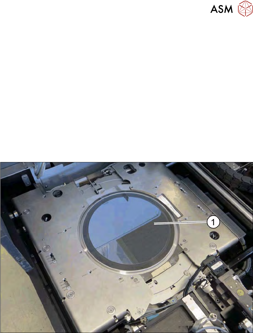
Fig.362: SIPLACE SWS wafer stretcher with stretched wafer foil
1. Stretched wafer foil in the SIPLACE SWS wafer stretcher
12 Wafer stretcher
12.1 Explanation of the wafer stretcher
268 Service Manual SIPLACE Wafer System (SWS) 11/2018
Detailed description
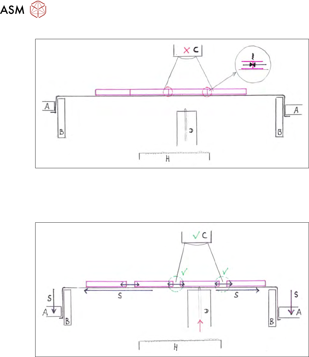
Fig.363:
While picking dies from a wafer, there is a danger that the die could begin to tilt. This can be
caused by an irregular adhesion of the die on the foil or an eccentric positioning of the needle. In
the case of dies which are positioned closely to one another, the neighboring die could be touched
and mutual damage can not be ruled out.
The limited space also makes it difficult for the Vision system (C) to recognize things!
Fig.364:
To prevent this, the wafer foil is stretched before the die is picked. This increases the distances
between the dies on the foil and makes it possible to pick dies without risks. The larger distances
between the dies also makes it easier for the Vision system (C) to recognize them.
The foil is stretched (S)by moving the downholder plate (A) downwards. This pulls the foil over the
stretcher ring (B), thereby stretching the entire foil (S). The adhesion of the die on the wafer foil in-
creases the space between the dies.
The edges of the dies no longer rub against one another. Reliable Vision recognition (C) of dies is
also possible, plus the ejection procedure (D) and pickup process can be successfully completed.