00195982-03_SM_SWS_EN.pdf - 第82页
5 Basic frame – X/Y unit 5.3 Replacing parts 82 Service Manual SIPLACE Wafer System (SWS) 11/2018 Fig.67: ► Carefully lift the motor and push the complete spindle unit over the base plate edge. Lift the motor only until…
5 Basic frame – X/Y unit
5.3 Replacing parts
Service Manual SIPLACE Wafer System (SWS) 11/2018 81
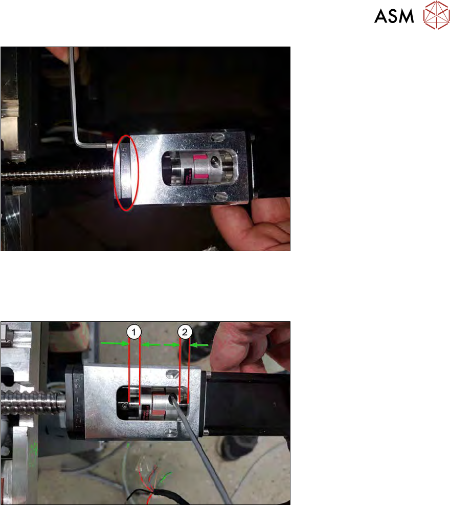
Fig.65:
► Carefully push the coupling plate-motor-coupling unit over the spindle.
► Pay attention to the alignment of the engraving on the spindle plate.
► Tighten the four fastening screws. Secure the screws with Loctite 243.
Fig.66:
► Adjust the coupling.
The distances should be approx. 6mm (1) and 4mm (2).
► Tighten the two clamping screws on the coupling!
5 Basic frame – X/Y unit
5.3 Replacing parts
82 Service Manual SIPLACE Wafer System (SWS) 11/2018
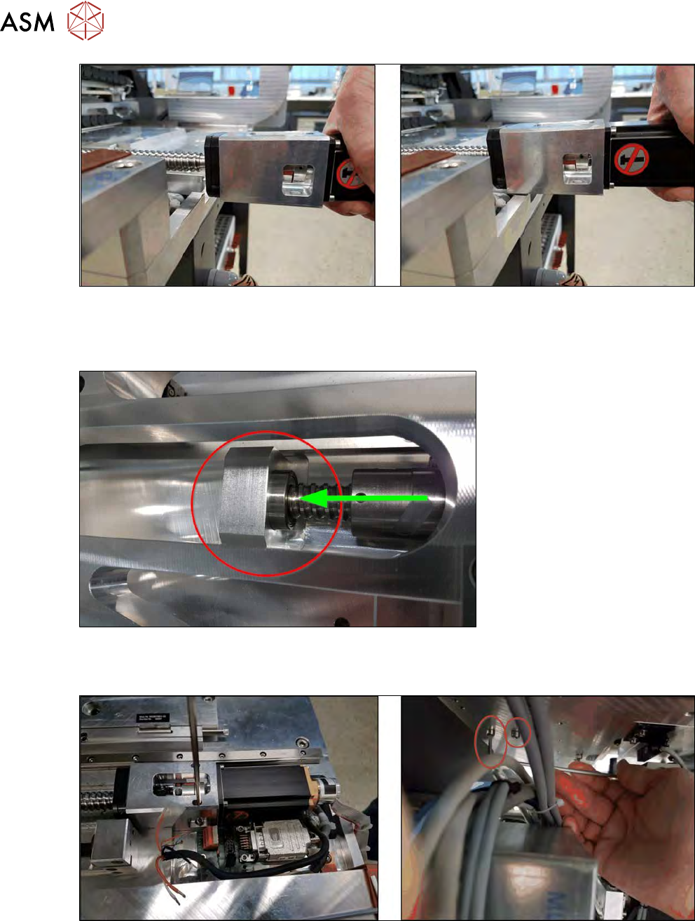
Fig.67:
► Carefully lift the motor and push the complete spindle unit over the base plate edge.
Lift the motor only until the coupling plate can scrape over the edge of the base plate. This en-
sures that the shaft is bent as little as possible.
Fig.68:
► Make sure that the back spindle bearing slides easily into the bearing shell when you push the
spindle unit in!
Fig.69:
► Slightly tighten the four screws (2x top and 2x bottom) so that the coupling plate can still be
moved. Secure the screws with Loctite 243.
5 Basic frame – X/Y unit
5.3 Replacing parts
Service Manual SIPLACE Wafer System (SWS) 11/2018 83
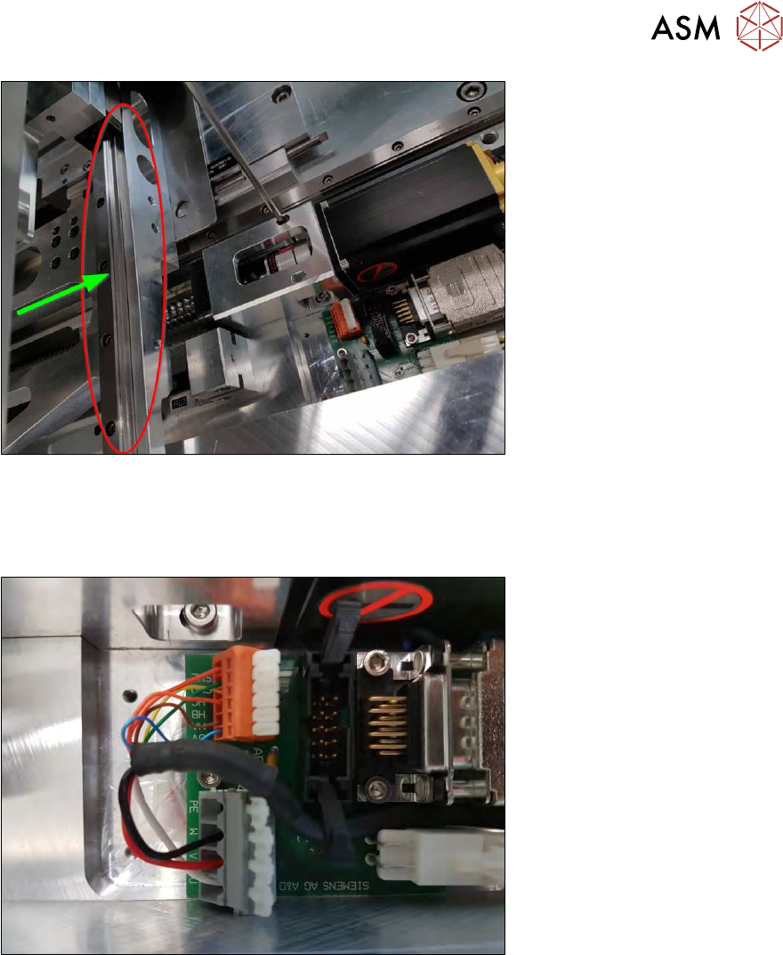
Fig.70:
► Manually pull the complete wafer table unit in the direction of the Y motor.
ð The spindle will now align itself with the coupling plate.
► Tighten the four screws fastening the coupling unit (2x top and 2x bottom).
Fig.71: