00195982-03_SM_SWS_EN.pdf - 第192页
9 Wafer change system 9.1 Magazine lift 192 Service Manual SIPLACE Wafer System (SWS) 11/2018 9.1 Magazine lift ● Magazine lift SWS12 (1/3) [00387216-xx] ● Magazine lift SWS12 (2/4) [00386436-xx] Fig.251: Magazine lift …
9 Wafer change system
Service Manual SIPLACE Wafer System (SWS) 11/2018 191
9 Wafer change system
There are two different versions, which vary only in their mirrored arrangement of the modules, and
that depend on the location. There are two different versions for the gripper, for locations 1/3 and
location 2/4.
●
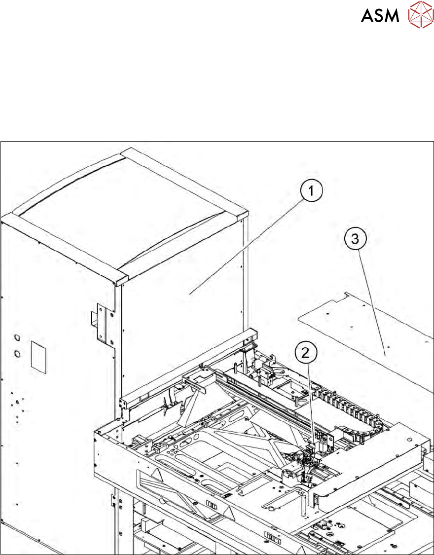
Wafer change system SWS12 (1/3) [00387216-xx]
●
Wafer change system SWS12 (2/4) [00386432-xx]
Fig.250: Wafer change system
1. Magazine lift
2. Gripper
3. Gripper cover
9 Wafer change system
9.1 Magazine lift
192 Service Manual SIPLACE Wafer System (SWS) 11/2018
9.1 Magazine lift
●
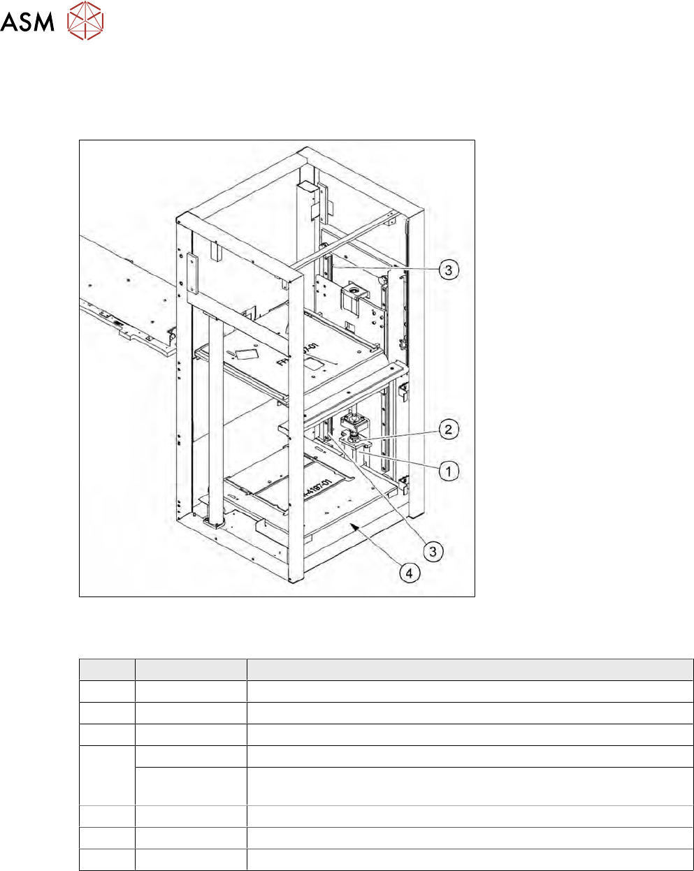
Magazine lift SWS12 (1/3) [00387216-xx]
●
Magazine lift SWS12 (2/4) [00386436-xx]
Fig.251: Magazine lift
Overview of spare parts
Item Item no. Designation
03066505-01 Diffuse mode sensor (wafer slot sensor)
00387493-01 Diffuse mode sensor (lift crash sensor)
4 00385143-01 Board DMC.INT1 Rev.0
3 03106448-01 Elastomer coupling without play d9,d10
Long metal bellows coupling DKN 20-32 10 9 (for short recirculating
ball screw)
1 03076559-01 Motor
3 03076606-01 Inductive sensor NBB2-F29-A2
03076689-xx 2 microswitches Saia Burgess XCG3-S1Z1 with cables
9.1.1 Replacing spare parts
9.1.1.1 Preparations
All tasks can be performed in the fitted state.
► Open the door.
► Remove the locking screw.
► Swing the front cover open to the right or left (depending on the variant).
9 Wafer change system
9.1 Magazine lift
Service Manual SIPLACE Wafer System (SWS) 11/2018 193
9.1.1.2 Replacing the motor
DANGER
Increased risk of injury when loosening the motor brake.
The lift is heavy (approx. 80 kg) and secured with a motor brake. When the motor is cur-
rent-free and the grub screw is loosened on the motor shaft coupling, the lift will move down
on the spindle without braking.
► Remove the magazine plate in the lift, if present.
► Support the lift with a suitable object (e.g. a stable wooden block) so that it can not
move downwards.
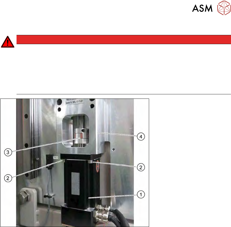
Fig.252: Motor with magazine lift coupling (short recirculating ball screw fitted)
Removal
► Unplug the motor and encoder cables from the motor (1).
► Loosen the grub screw holding the coupling (3) on the motor shaft.
► Remove the four screws (2) on the mounting unit (4) and pull the motor (1) down and out.
► Check the coupling for damage and replace if necessary.
Installation
► Push the motor and mounting plate into the spindle coupling.
► Align the motor and shaft on the spindle so that they are in line.
► Loosely tighten the four screws (2) on the mounting unit (4).
► The coupling may not have any offset. Check the concentricity. There is otherwise a risk that
the coupling could break.
► Tighten the grub screw on the coupling (3).
► Tighten the four screws (2) on the mounting unit (4).
► Plug the motor and encoder cables into the motor (1).
► Fix and gather the cables together with cable ties, where necessary. Make sure that the
cables do not rub against any part or get trapped.