00195982-03_SM_SWS_EN.pdf - 第477页
18 Appendix 18.1 Specification: emergency STOP Service Manual SIPLACE Wafer System (SWS) 11/2018 477 18 Appendix 18.1 Specification: emergency STOP 18.1.1 Switching elements ● Emergency STOP switching device ( K3 ) 3TK28…
17 Tips and tricks
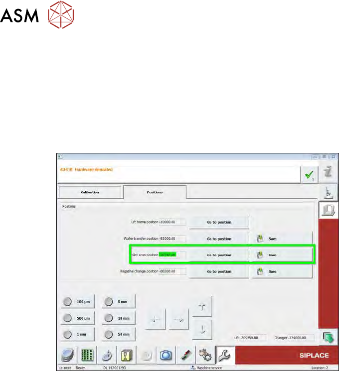
17.3 Wafers are recognized in the wrong slot of the magazine
476 Service Manual SIPLACE Wafer System (SWS) 11/2018
17.3 Wafers are recognized in the wrong slot of the magazine
Error description
●
Scaling factor "distance magazine plate-slot" appears to be too small.
e.g. wafer in slot 25 is recognized at slot 10 or wafer at slot 10 is recognized at slot 2.
●
When the slot is approached again, another value is addressed and saved.
Procedure
Fig.745:
► Check the clamping screw on the coupling of the wafer lift drive.
If this has loosened, the motor axis or coupling will slip and the values of the rotary encoder
for the motor will no longer match the real distances moved by the spindle.

18 Appendix
18.1 Specification: emergency STOP
Service Manual SIPLACE Wafer System (SWS) 11/2018 477
18 Appendix
18.1 Specification: emergency STOP
18.1.1 Switching elements
●
Emergency STOP switching device (K3) 3TK28-21-1CB30 / DC24V / autostart / 3S / 1Ö
●
Emergency STOP mushroom-head pushbutton / d = 40mm / rotary release / 1S / 2Ö
●
Relay 24VDC (K4) to reset emergency STOP with program (set output 1)
●
Control lamp for on/off function emergency STOP
●
Relay 24VDC (K5) feeder presence - signal > set output 16
●
2 power contactors (K1, K2), coil 24VDC / switching capacity 25A / with additional unit
●
1 time relay unit release-delayed (500ms), can be attached to power contactor K1
External SWS service box [03075503‑xx] (connection at connector X1x3)
●
Emergency STOP mushroom-head pushbutton / d = 40mm / rotary release / 1Ö
●
Start button with lamp (white= operating display) to reset the emergency STOP
●
Relay 24VDC / 1S for external emergency STOP latching function
18.1.2 External connection to SIPLACE
X113 = location-1
X123 = location-2
X133 = location-3
X143 = location-4
Wago connector, 12 pin, type 721-612
●
Pin-1 = ground external >> PE feeder
●
Pin-2 = +24V / external
●
Pin-3 = SIPLACE emergency STOP loop input
●
Pin-4 = SIPLACE emergency STOP loop output
●
Pin-5 = SWS emergency STOP loop output
●
Pin-6 = SWS emergency STOP loop input
●
Pin-7 = feeder presence signal (+24V / external from K5)
●
Pin-8 = no function
●
Pin-9 = emergency STOP message (+24V / external) from feeder to SIPLACE > input
●
Pin-10 = no function
●
Pin-11 = no function
●
Pin-12 = no function
18.1.3 Input/output checklist
●
Input 1 = 1 > emergency STOP mushroom-head pushbutton SWS = not pressed
●
Input 16 = 1 > emergency STOP loop SWS for switching device K3 is closed
●
Input 1 = 0 / IN16 = 0 > emergency STOP activation from die feeder (internal)
●
Input 1= 1 / IN16 = 0 > emergency STOP activation from SIPLACE (external)
●
Input 15 = 1 > contactor K1/K2 = on, 48VDC control for motor amplifier = OK
●
Output 1 = K4 (on/off 150 ms) > reset emergency STOP > start SWS
●
Output 16 = 1 > K5 = on, feeder present signal to the SIPLACE

18 Appendix
18.1 Specification: emergency STOP
478 Service Manual SIPLACE Wafer System (SWS) 11/2018
18.1.4 Function description
After the SWS has switched on, the emergency STOP switching device will be activated K3 but
only under the following conditions:
●
Emergency STOP loop for SWS is closed > emergency STOP button for SWS is disabled.
●
Emergency STOP loop for SIPLACE is closed > cover closed, start button pressed.
●
The starting states of the inputs IN1 and IN16 are set to one.
The reset/start loop is then closed by activating the start relay K4 set-output1 (on/off 150ms).
The activated emergency STOP switching device K3 switches the contactors K1/K2 on (24VDC
coil).
The intermediate cycle voltage 48 VDC to the motor power ratings DMC-19540(20) is made avail-
able via the contactor contacts K1/K2 (25A).
The motor voltage is then activated via the motor controller enable signal. The ABORT signal (mo-
tor amplifier DMC-19540(20)) is disabled via the K2normally closed contact.
Once the emergency STOP has been activated, the ABORT contact against GND/K2 will be
closed.
The operational readiness lamp (white) is switched on via the emergency STOP switching device.
The 24VDC emergency STOP voltage is made available via the contactor K1 at terminal X3-17.
The main valve compressed air Y1/PRS for the die ejector Z lift is switched on via the normally
open K2 contact.
When the emergency STOP is enabled, the contact is open and the compressed air (DE Z lift) will
be switched off.
The compressed air valves for the cylinder of the tool Z (pickup) and tool X (die attach unit) are
switched off via the contactors K1 and K2 in the event of an emergency STOP. During the emer-
gency STOP function, the drives are switched off and the tools are held in a secure position by
spring force.
The GND/K2 signal, which is open during the emergency STOP via the K2 switches the braking
magnets for the wafer lift function off. The brake is then active and the wafer lift is held in position.
When the emergency STOP switching device has been enabled, there are three signals issued
one= 24VDC.
●
IN1 = emergency STOP button
●
IN16 = emergency STOP loop SWS
●
IN15 = 48 V DC control for motor amplifier > signal provision in series via K1/K2 and opto-
coupler OK6.
In the event of an emergency STOP, the contactors K1/K2 will switch off with a delay of µm
500ms. This means that the control system has a residual runtime for a controlled stop function.
18.1.4.1 Emergency STOP
Case 1: emergency STOP with mushroom-head pushbutton SWS
The emergency STOP loop for the SIPLACE and the emergency STOP loop for the SWS will be in-
terrupted and the corresponding emergency STOP switching devices in each case will switch the
power contactors off (delayed 500ms).
The signal messages (IN1 = emergency STOP button, IN16 = emergency STOP switching device,
IN15 = 48VDC via K1/ K2) will be zero.
The operational readiness lamp (white) will be switched off.
The emergency STOP message for the SIPLACE will be interrupted via the mushroom-head push-
button at the connector X1x3 (+24V / external = pin-2 and emergency STOP message = pin-9).
The SIPLACE can therefore recognize the location at which the emergency STOP button was
pressed.