00195982-03_SM_SWS_EN.pdf - 第144页
7 Die ejector 7.3 Replacing spare parts 144 Service Manual SIPLACE Wafer System (SWS) 11/2018 Fig.176: Die ejector (example of SWS 2/4 shown) ► Insert the left hand into the die ejector recess, lift it gently and put th…
7 Die ejector
7.3 Replacing spare parts
Service Manual SIPLACE Wafer System (SWS) 11/2018 143
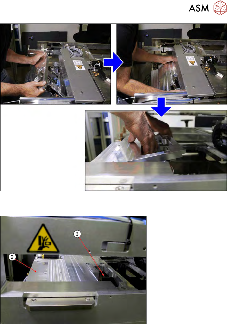
Fig.174:
► Thread the base plate in and position it on the SWS plate. Make sure that it does not bump
against anything.
Fig.175:
► Place the base plate down on the SWS plate (2). The die ejector recess (3) points in the direc-
tion of the wafer lift.
7 Die ejector
7.3 Replacing spare parts
144 Service Manual SIPLACE Wafer System (SWS) 11/2018
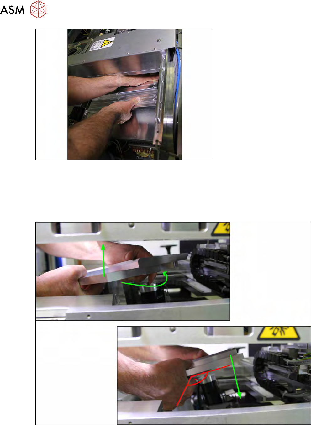
Fig.176: Die ejector (example of SWS 2/4 shown)
► Insert the left hand into the die ejector recess, lift it gently and put the right hand under the
front side.
The diagram is for a die ejector with an SWS 2/4.
When using an SWS 1/3, you need to insert the right hand into the recess and hold the front
side with the left hand.
SWS 2/4
Fig.177:
► Lift the base plate slightly and turn this by approx. 90° to the left (anticlockwise).
► Carefully lower the base plate.
7 Die ejector
7.3 Replacing spare parts
Service Manual SIPLACE Wafer System (SWS) 11/2018 145
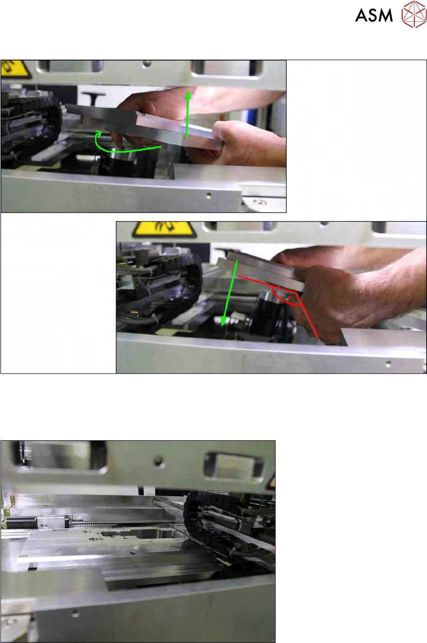
SWS 1/3
Fig.178:
► Lift the base plate slightly and turn this by approx. 90° to the right (clockwise).
► Carefully lower the base plate.
Fig.179: SWS base plate