00195982-03_SM_SWS_EN.pdf - 第52页
3 SIPLACE wafer system (SWS) function 3.2 Basic die presentation process 52 Service Manual SIPLACE Wafer System (SWS) 11/2018 3.2.6 Embedded wafer level ballgrid array (eWLB/WLFO) process Embedded wafer level ballgrid ar…
3 SIPLACE wafer system (SWS) function
3.2 Basic die presentation process
Service Manual SIPLACE Wafer System (SWS) 11/2018 51
3.2.4 Ejection procedure
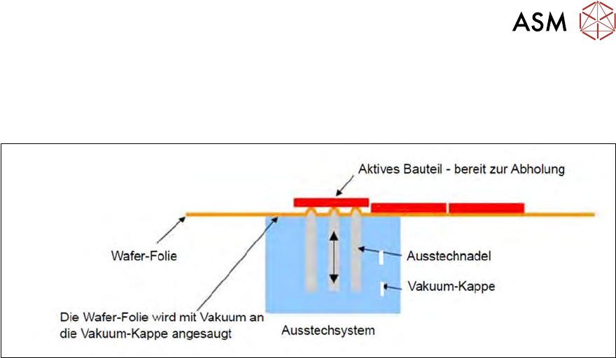
Once the die has been centered using the ejector system, it can be released from the wafer foil us-
ing needles and transferred to the flip unit. While the needles release the die from the foil, the wafer
foil is moved towards the ejection system by means of suction.
Fig.31: Die presentation process
The following equipment is needed for this process:
●
Ejection system with exchangeable ejector tool
3.2.5 Pickup process
During the pickup process, the die is transferred to the tool and to the nozzle of the flip unit. The flip
unit transfers the die on it either to the placement head (flip chip process) or to the die attach unit
(die attach process).
The die attach unit rotates the die again and then presents it to the placement head. The following
equipment is needed for this process step:
●
Flip unit
●
Die attach unit (optional)
3 SIPLACE wafer system (SWS) function
3.2 Basic die presentation process
52 Service Manual SIPLACE Wafer System (SWS) 11/2018
3.2.6 Embedded wafer level ballgrid array (eWLB/WLFO) process
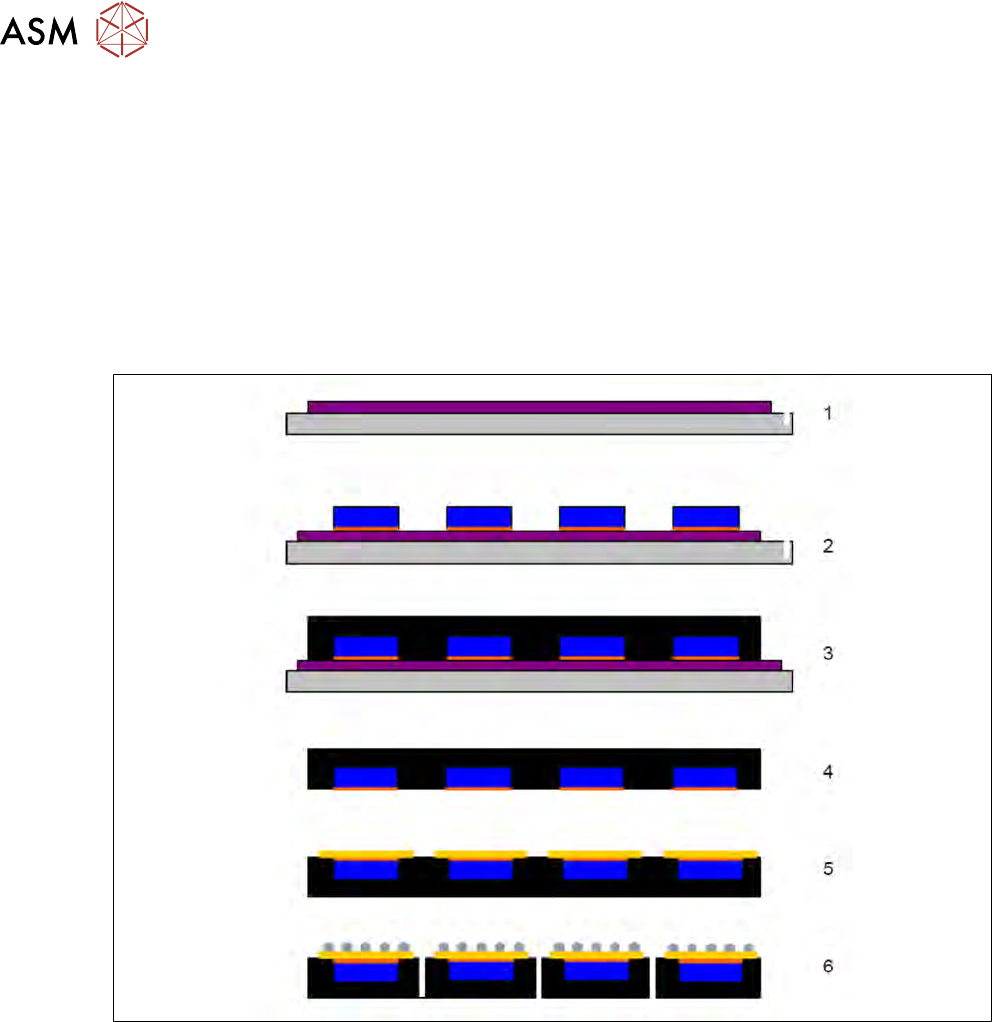
Embedded wafer level ballgrid array is a packaging technology which makes it possible to produce
thin components with excellent electrical conduction with a 'chip fan out'. This means that the area
used for the connection pads is larger than the actual silicon, making sufficient space available for
the SMD process.
In this process, the chip components are placed with the active surface pointing downwards ("face
down") on a carrier with double-sided adhesive tape. After placement, this structure is molded.
After the die bond process of the carrier material, wafer structuring processes are used to create
the electrical contacts. In these, the molded area around the silicon is used as the carrier material
for "conductor tracks" ("fan out"). Finally, the components are tested, labeled and, for example,
packed in tapes.
Fig.32: Steps in the embedded wafer level ballgrid array process
1. The thermal release tape is laminated onto the metal carrier.
2. The active side of the wafer is placed face down onto the thermal release tape (flip chip)
3. Molding takes place under pressure, hardening at 150°C
4. Release
5. Redistribution layer (RDL)
6. Balling and single
7. Test, mark, pack
3 SIPLACE wafer system (SWS) function
3.3 Pick and transfer process in detail
Service Manual SIPLACE Wafer System (SWS) 11/2018 53
3.3 Pick and transfer process in detail
3.3.1 Flip chip segment 1 (nozzle)
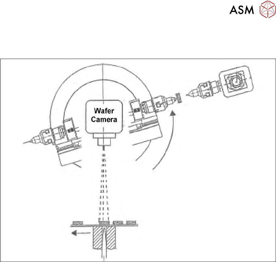
Fig.33: Flip chip segment 1 (nozzle)
●
The wafer X-Y travels to the next chip.
●
The flip chip rotary unit segment 1 turns to the handover position "Die Attach".
Image recognition of the next chip is performed from the camera "free" position.