00195982-03_SM_SWS_EN.pdf - 第173页
8 Flip unit 8.1 Overview of main assemblies Service Manual SIPLACE Wafer System (SWS) 11/2018 173 8 Flip unit According to the location there are two different variants that only differ in their mirrored arrange- ment of…
7 Die ejector
7.6 Converting the bayonet needle ejector unit (old version) to the magnetic needle ejector unit (current
172 Service Manual SIPLACE Wafer System (SWS) 11/2018
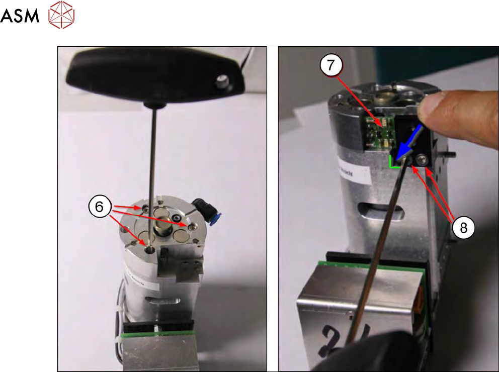
Fig.223:
The cable for the fork light barrier board does not need to be unplugged for removal (the diagram
without cable is just an example).
► Fasten the centering unit into place with the three Allen screws (6). Use the screws from the
unit you dismantled before.
► Fit the fork light barrier board (7) into place with the two Allen screws(8). Press the board into
the bottom left corner and tighten the two Allen screws.
► Connect the vacuum hose to the centering unit.
Calibrating
The following calibrations must be performed after the conversion.
●
Position "calibration of ejection needle"
This calibrates the height of the needle so that it is flush with the upper edge of the black ejec-
tion cap (see 15.3.2.5 "Calibration – die ejector needle" [}385]).
●
Check the needle position in the X and Y directions.
The needle tip must correspond with the camera center point (red cross in Vision view) (see
15.3.2.4 "Calibration – segment offset calibration in X direction" [}379]).
8 Flip unit
8.1 Overview of main assemblies
Service Manual SIPLACE Wafer System (SWS) 11/2018 173
8 Flip unit
According to the location there are two different variants that only differ in their mirrored arrange-
ment of the modules.
●
Flip unit SWS12 (1/3) [00386916-xx]
●
Flip unit SWS12 (2/4) [00385832-xx]
The flip unit is located on the basic SWS unit.
8.1 Overview of main assemblies
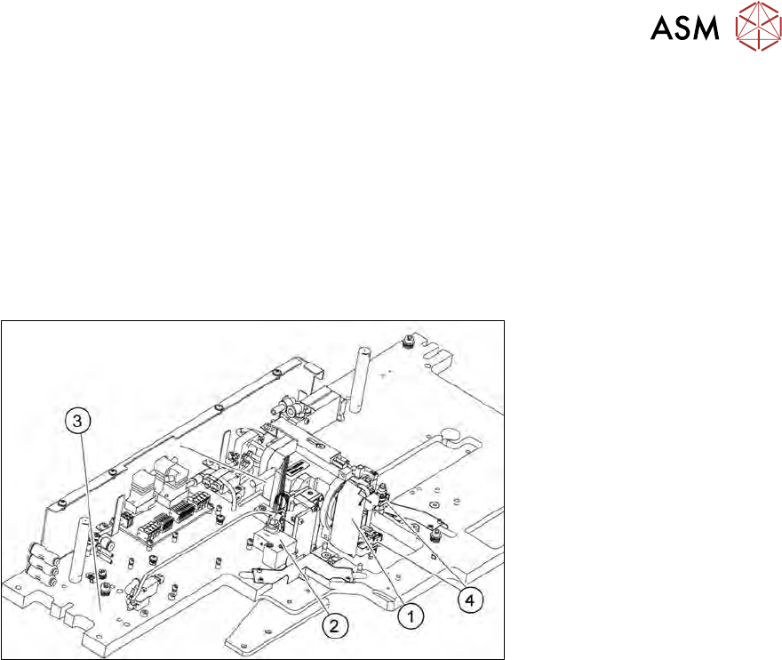
Fig.224: Main flip unit assemblies
1. Flip head
2. Return unit
3. Flip unit base plate
4. Nozzle support
8 Flip unit
8.2 Overview of spare parts
174 Service Manual SIPLACE Wafer System (SWS) 11/2018
8.2 Overview of spare parts
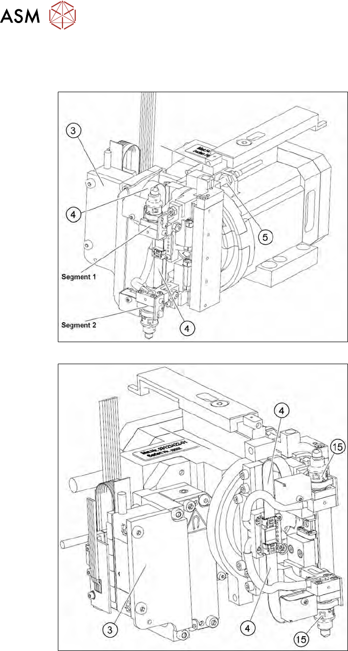
Flip head
Fig.225: Flip head - view from behind
Fig.226: Flip head - view from the front