00195982-03_SM_SWS_EN.pdf - 第149页
7 Die ejector 7.4 Mechanical adjustment of the needle position in the X/Y position Service Manual SIPLACE Wafer System (SWS) 11/2018 149 7.4.1.2 Preparatory tasks ► Switch the SWS on and initialize the system. ► Log your…
7 Die ejector
7.4 Mechanical adjustment of the needle position in the X/Y position
148 Service Manual SIPLACE Wafer System (SWS) 11/2018
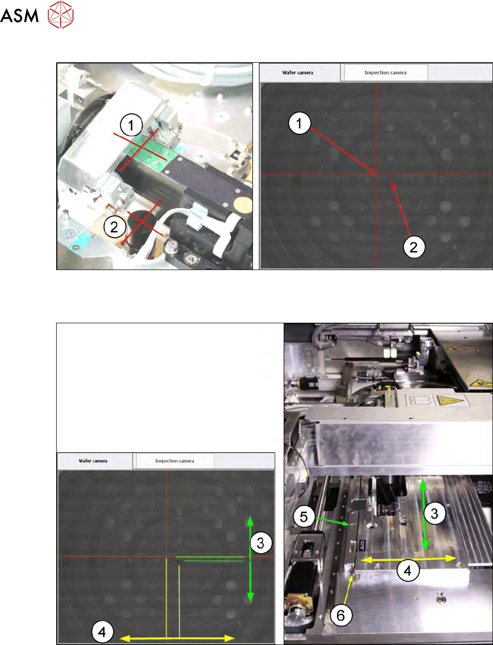
7.4.1.1 Explanation of the coordinate system
Fig.183:
(1) Camera center point (red cross)
(2) Center point of central needle in the ejection system (small, bright dot in the central drilled hole)
Fig.184:
(3) Y direction → movement of base plate in the direction of the wafer lift
(4) X direction → movement of base plate in the direction of the SWS sides
(5) Adjusting screw for moving the base plate in the Y direction (Allen key 4mm)
(6) Adjusting square shaft for moving the base plate in the X direction (fork wrench SW5)
7 Die ejector
7.4 Mechanical adjustment of the needle position in the X/Y position
Service Manual SIPLACE Wafer System (SWS) 11/2018 149
7.4.1.2 Preparatory tasks
► Switch the SWS on and initialize the system.
► Log yourself in as SIPLACE Service.
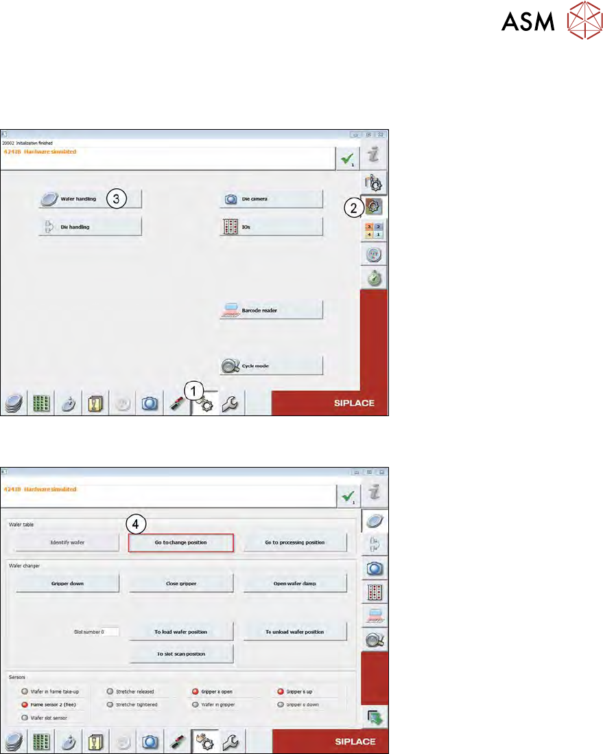
Fig.185:
► Switch menu to Wafer Handling (1 to 3).
Fig.186:
► Move the wafer table to the change position (4).
► Leave this menu in the main view.
7 Die ejector
7.4 Mechanical adjustment of the needle position in the X/Y position
150 Service Manual SIPLACE Wafer System (SWS) 11/2018
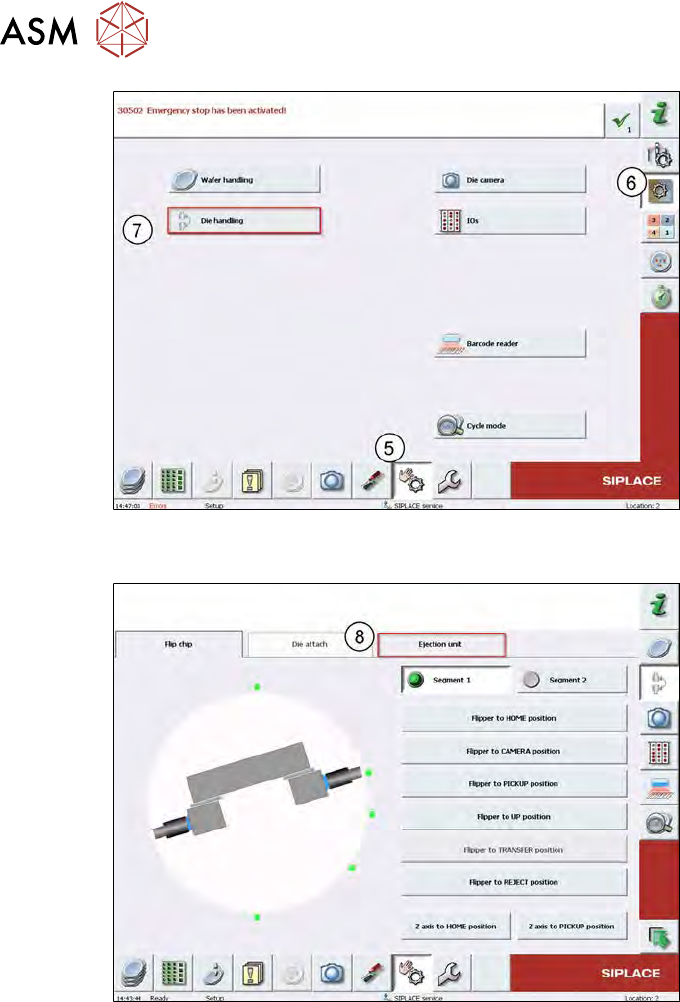
Fig.187:
► Change the menu with steps (5) to (7) until you get to the Die Handlingmenu.
Fig.188:
► Change to the Ejection unit (8).