00195982-03_SM_SWS_EN.pdf - 第66页
4 SWS installation and removal for SIPLACE CA machines 4.3 Swinging up the magazine lift 66 Service Manual SIPLACE Wafer System (SWS) 11/2018
4 SWS installation and removal for SIPLACE CA machines
4.3 Swinging up the magazine lift
Service Manual SIPLACE Wafer System (SWS) 11/2018 65
4.3 Swinging up the magazine lift
When performing service work to the parts which can not be accessed from above, you need to
make the inside of the SWS accessible from the front.
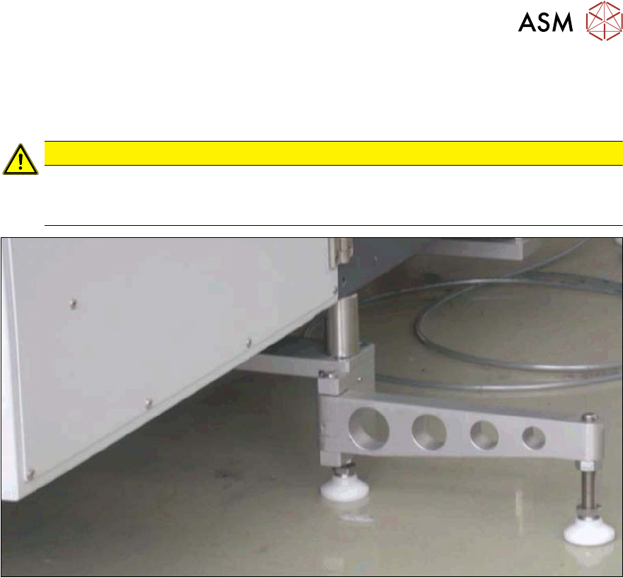
CAUTION
Risk of magazine lift tilting
► Make sure that the SWS support foot is folded out to the side before you swing the
magazine lift up. Otherwise, there is a risk that the magazine lift may tilt over.
Fig.43: Support leg when folded open
► Fold the SWS support foot out to the side.

4 SWS installation and removal for SIPLACE CA machines
4.3 Swinging up the magazine lift
66 Service Manual SIPLACE Wafer System (SWS) 11/2018
5 Basic frame – X/Y unit
5.1 Function description
Service Manual SIPLACE Wafer System (SWS) 11/2018 67
5 Basic frame – X/Y unit
This assembly consists of the two individual modules basic frame and X/Y unit.
According to the location there are two different variants that only differ in their mirrored arrange-
ment of the modules.
●
Basic frame SWS12 (1,3) [00386774-xx] and X/Y unit SWS12 (1,3) [00386776-xx]
●
Basic frame SWS12 (2,4) [00385830-xx] and X/Y unit SWS12 (2,4) [00385864-xx]
These assemblies are not defined as spare parts.
5.1 Function description
This complete assembly has a motor unit each for the X and the Y direction. These are servo mo-
tors with an encoder positioning. The drive for the axes is realized via spindles with recirculating
ball bearings. The connection between motor and spindle is realized via elastomer couplings.
The X/Y unit helps to position the wafer over the die ejector or to operate the wafer lift.
5.2 Complete overview
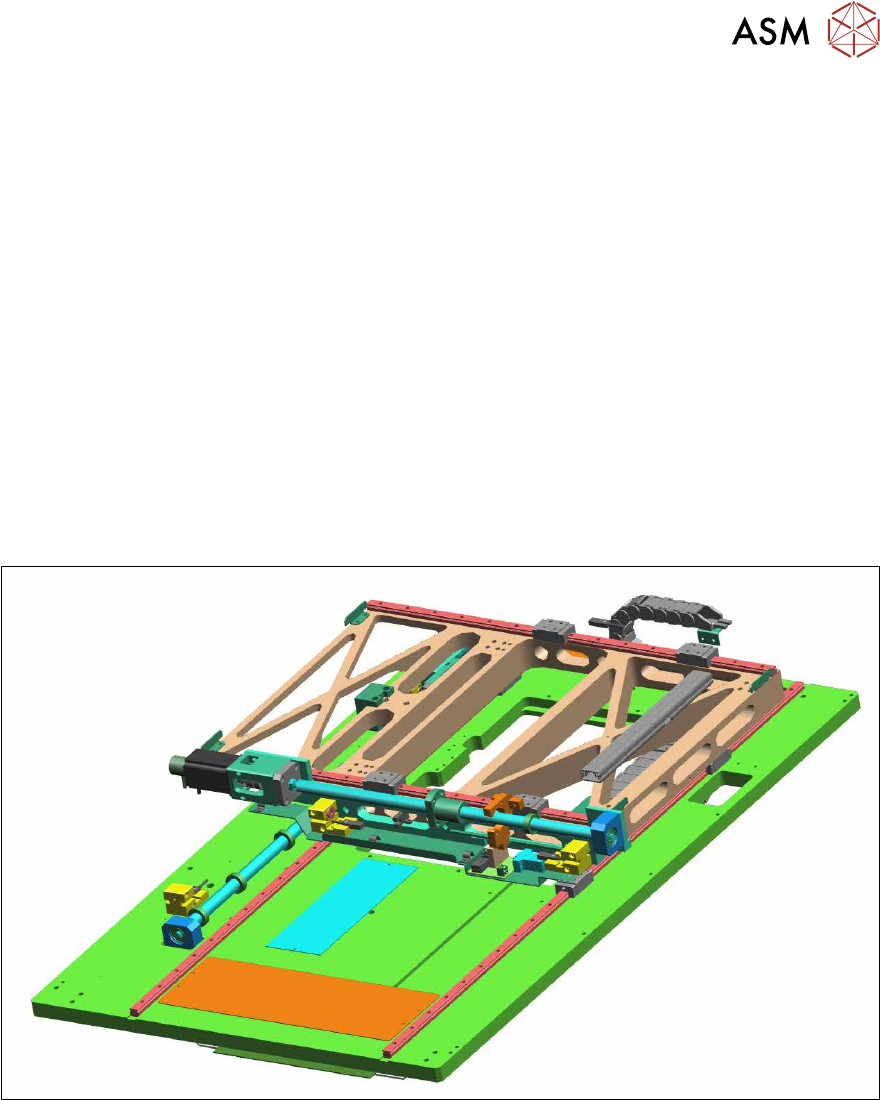
Fig.44: Complete assembly "Base plate – X/Y unit" for an SWS 1/3