00195982-03_SM_SWS_EN.pdf - 第49页
3 SIPLACE wafer system (SWS) function 3.2 Basic die presentation process Service Manual SIPLACE Wafer System (SWS) 11/2018 49 3.2.1 Flip chip process The flip chip process is the standard method for SWS. The die is rotat…
3 SIPLACE wafer system (SWS) function
3.2 Basic die presentation process
48 Service Manual SIPLACE Wafer System (SWS) 11/2018
3.2 Basic die presentation process
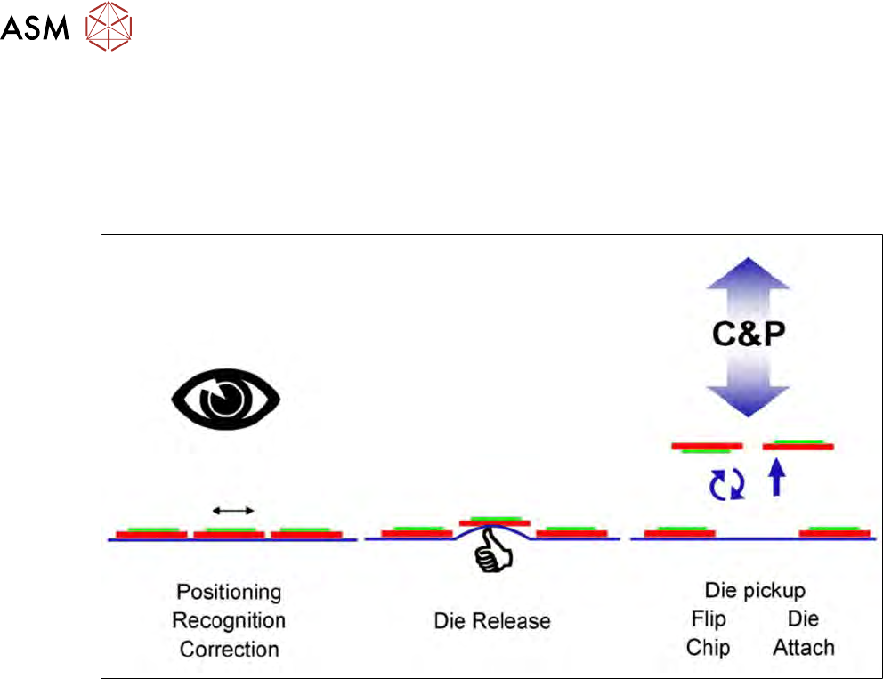
The basic die presentation process supported by the SWS can be divided into three main steps:
●
Die recognition and positioning for ejection (incl. inkspot recognition or wafer map)
●
Ejection procedure
●
Pickup procedure for die attach or flip chip processing.
Fig.28: Basic die presentation process
There are two main ways to place dies, the flip chip and the die attach process.
3 SIPLACE wafer system (SWS) function
3.2 Basic die presentation process
Service Manual SIPLACE Wafer System (SWS) 11/2018 49
3.2.1 Flip chip process
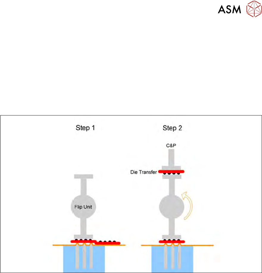
The flip chip process is the standard method for SWS. The die is rotated by 180° before placement
(face down placement).
The flip chip method is a rapidly growing technology. This process is primarily used for consumer
electronics assemblies (e.g. processors, graphics processors, memory).
The die inputs/outputs (I/O) are directly attached to the printer circuit board, which has several be-
nefits compared to the conventional die attach process:
●
Less space needed
●
Faster transmission of signals
●
Higher density of I/O per component
Fig.29: Flip chip process
The steps of the flip chip process are as follows:
●
Step 1: Die release
●
Step 2: The die is rotated by 180° and is passed on to the placement head. Parallel to this, the
next die is taken up by the second nozzle of the flip unit.
3 SIPLACE wafer system (SWS) function
3.2 Basic die presentation process
50 Service Manual SIPLACE Wafer System (SWS) 11/2018
3.2.2 Die attach process
The optional die attach unit is needed for the die attach process.
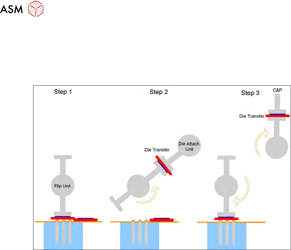
In this method, the die is placed in the same bottom/top orientation as it was on the wafer foil
("face-up" placement).
The die attach method is the traditionally established die placement procedure. Die attach requires
an additional step to create the connections between the die and the printed circuit board (wiring
connections).
Fig.30: Die attach process steps
The steps in the die attach process are as follows:
●
Step 1: Die release
●
Step 2: The die is rotated by approx. 130°and transferred to the die attach unit.
●
Step 3: The die attach unit rotates the die into the pickup position and transfers it to the place-
ment head. Parallel to this, the next die is picked up by the flip unit.
3.2.3 Die recognition and die positioning
The wafers are fixed to the wafer foil with a specific position and angular tolerance.
It is therefore not possible to place the die reliably in the center of the ejector unit without recogni-
tion and correction. This is particularly important for small dies, in order to ensure reliable ejection.
Furthermore, you may need to process only a selection of dies. A selection can be made by mark-
ing "bad" dies with an ink spot or by using a wafer map file for the relevant wafer.
The following equipment is needed for this process step:
●
2 axis wafer table for positioning
●
Wafer camera system for the die and for optional ink spot recognition
●
Optional wafer map system