00195982-03_SM_SWS_EN.pdf - 第94页
5 Basic frame – X/Y unit 5.3 Replacing parts 94 Service Manual SIPLACE Wafer System (SWS) 11/2018 Fig.91: ► Thread the coupling plate X motor unit over the coupling and onto the spindle. Always hold the fastening screw …
5 Basic frame – X/Y unit
5.3 Replacing parts
Service Manual SIPLACE Wafer System (SWS) 11/2018 93
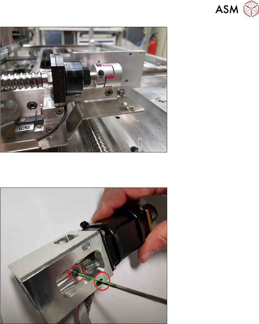
Fig.89:
► Push the coupling as far as the stop, onto the spindle shaft!
The label on the coupling should point in the direction of the spindle.
The writing on the spindle plate should point to the wafer lift, as shown in the diagram!
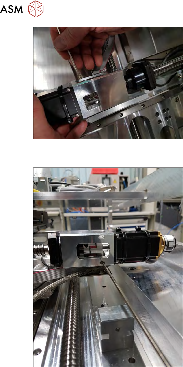
Fig.90:
► Place the lower front fastening screw into the coupling plate and hold it in position with an
Allen key!
5 Basic frame – X/Y unit
5.3 Replacing parts
94 Service Manual SIPLACE Wafer System (SWS) 11/2018
Fig.91:
► Thread the coupling plate X motor unit over the coupling and onto the spindle.
Always hold the fastening screw in position with the Allen key.
Fig.92:
► Now push the system together, so that the motor shaft slides into the coupling.
Always hold the fastening screw in position with the Allen key, so that the screw does not fall
out of the hole.
► Push the coupling plate back and forth until you find the threaded hole.
► Loosely tighten the fastening screw so that the coupling plate can still be moved.
► Now slightly tighten the second fastening screw on the coupling plate from the front. Secure
the screw with Loctite243.
5 Basic frame – X/Y unit
5.3 Replacing parts
Service Manual SIPLACE Wafer System (SWS) 11/2018 95
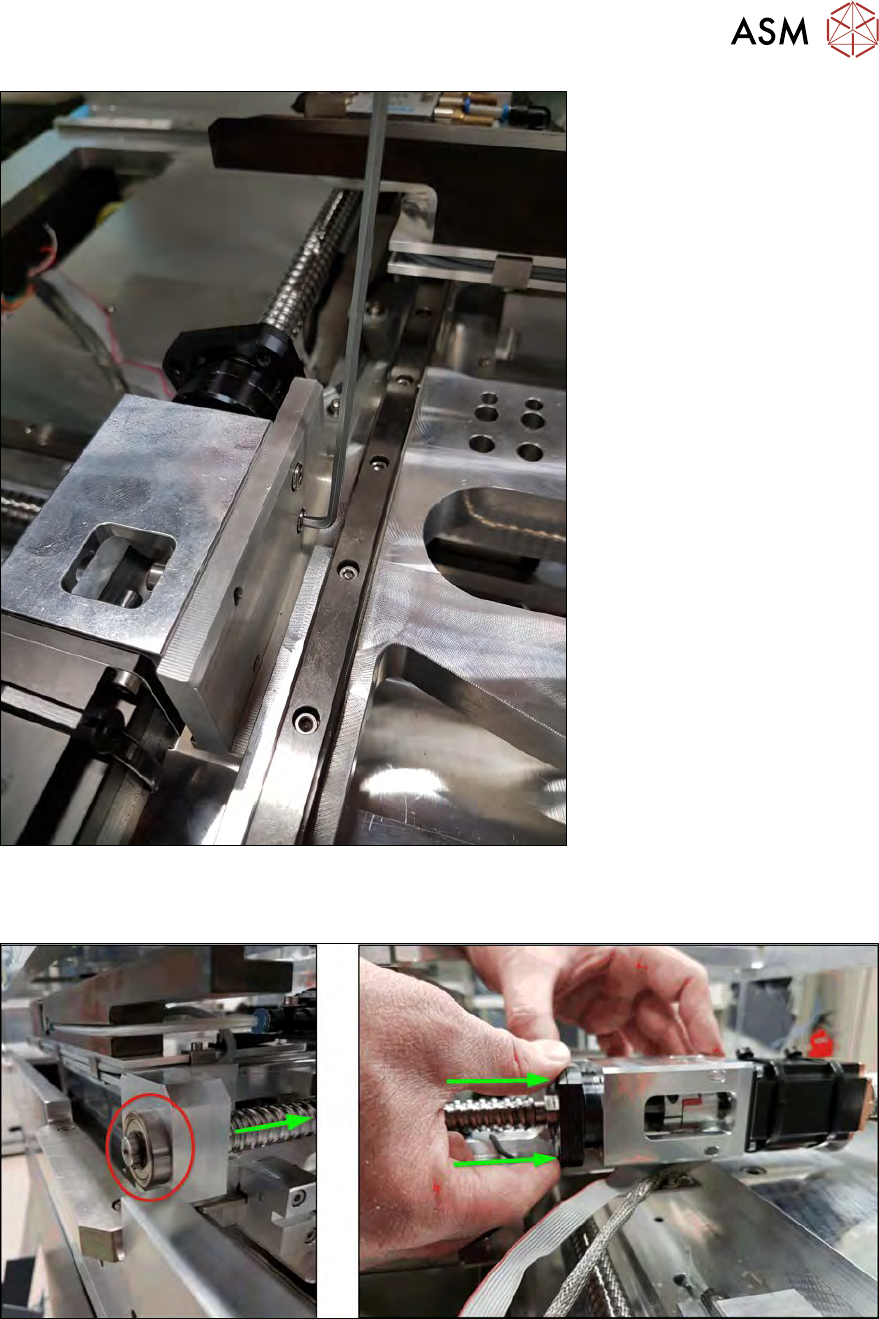
Fig.93:
► Now slightly tighten the two fastening screws on the rear (with shortened, modified Allen key).
Secure the screws with Loctite 243.
Fig.94:
► Now carefully press the spindle plate and the whole spindle into the coupling plate.
Make sure that the spindle bearing moves smoothly and easily into the bearing shell.