00195982-03_SM_SWS_EN.pdf - 第295页
12 Wafer stretcher 12.6 Fitting the wafer stretcher Service Manual SIPLACE Wafer System (SWS) 11/2018 295 Fig.417: ► Now carefully lift the wafer stretcher onto the X/Y table. Fig.418: ► Place the wafer stretcher about…
12 Wafer stretcher
12.6 Fitting the wafer stretcher
294 Service Manual SIPLACE Wafer System (SWS) 11/2018
12.6.2 Fitting the wafer stretcher to the guide trolley
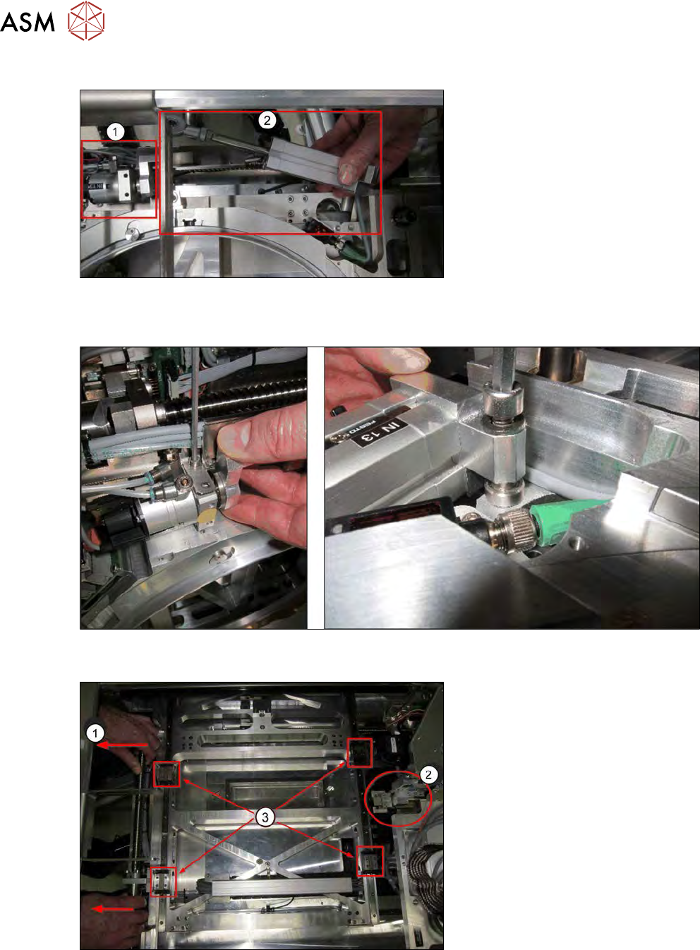
Fig.414:
► Dismantle and remove the clamping cylinder (1) and the lifting cylinder (2) from the wafer
stretcher. The diagram is only an example, as it shows the dismantled state in the SWS!
Fig.415:
► To dismantle, remove the two screws on the cylinders.
Fig.416:
► Pull the X/Y table fully over to the wafer lift side (1).
► Position the wafer changer (gripper) right at the back (2).
► Clean the surface of the guide trolleys (3).
► First position the guide trolleys roughly over the fastening holes in the wafer stretcher.
12 Wafer stretcher
12.6 Fitting the wafer stretcher
Service Manual SIPLACE Wafer System (SWS) 11/2018 295
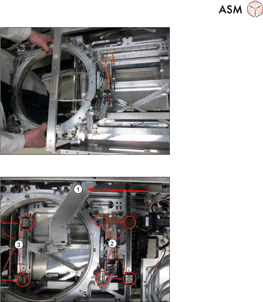
Fig.417:
► Now carefully lift the wafer stretcher onto the X/Y table.
Fig.418:
► Place the wafer stretcher about 2/3 onto the X/Y table.
► Pull the wafer changer (gripper) into the middle of the wafer stretcher (1).
► Align the guide trolleys to the fastening holes in the wafer stretcher (2 and 3).
12 Wafer stretcher
12.6 Fitting the wafer stretcher
296 Service Manual SIPLACE Wafer System (SWS) 11/2018
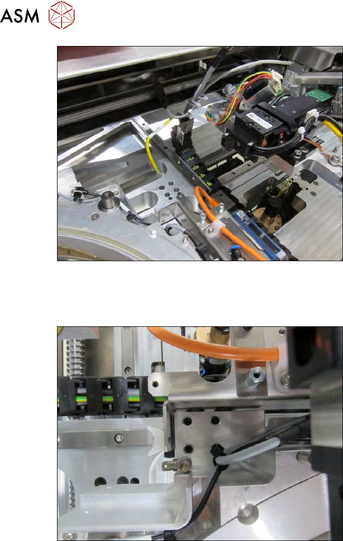
Fig.419:
► Roll out the cable chain and fix into place with the cables to an upper assembly.
This makes it easier to fit the wafer stretcher onto the guide trolleys, as you do not need to lift it
over the rolled-up cable chain.
Fig.420:
► Now carefully lift the wafer stretcher onto the four guide trolleys.
► Position the four guide trolleys so that the fastening holes in the wafer stretcher are in a line
with the threaded holes in the guide trolleys.
► Screw all four guide trolleys tightly into place.
You now need to establish the connection between the wafer stretcher and the drive spindle in the
X direction as follows: