00195982-03_SM_SWS_EN.pdf - 第127页
7 Die ejector 7.3 Replacing spare parts Service Manual SIPLACE Wafer System (SWS) 11/2018 127 Rotary direction for base plate SWS 2/4 Fig.144: ► Carefully turn the base plate to the right (clockwise), until the plate is…
7 Die ejector
7.3 Replacing spare parts
126 Service Manual SIPLACE Wafer System (SWS) 11/2018
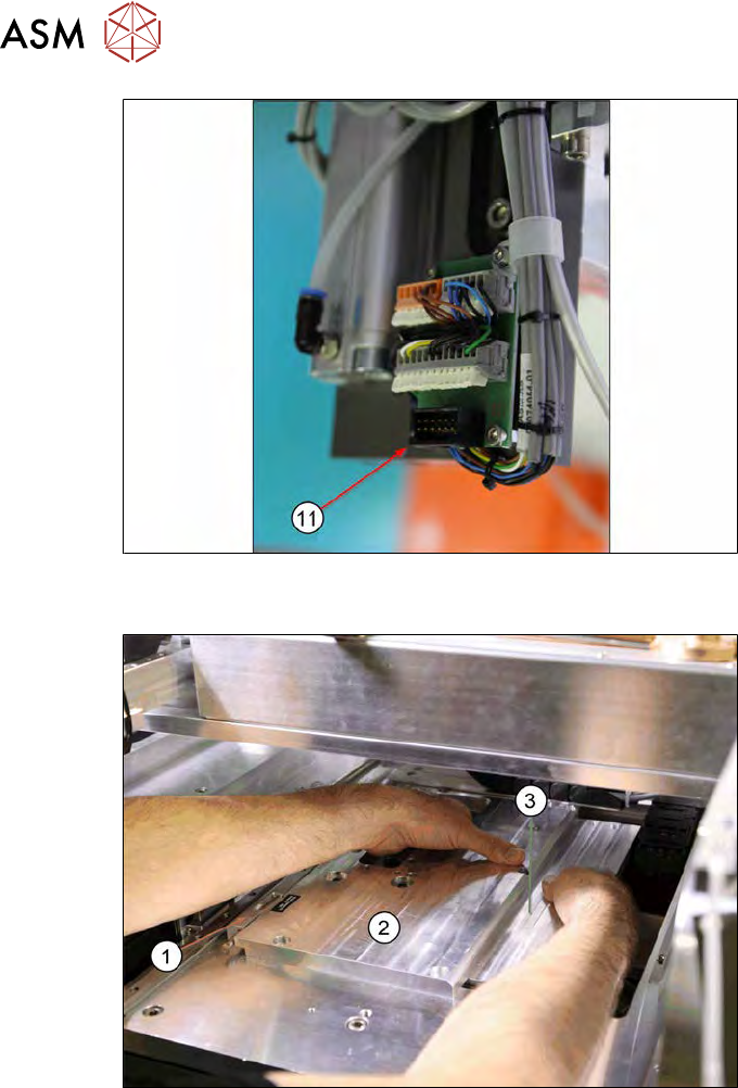
Fig.142:
► Disconnect the cable X11.2 from connector X11 (11) for the IO board!
Fig.143:
The diagram shows the die ejector base plate for an SWS 2/4 from the direction of the dismantled
nozzle changer. In this case, the eccentric shaft(1) is to the left of the base plate.
► Grasp the base plate (2) at the cut-out recesses and lift the base plate(3).
You need to turn the base plate to remove it. The direction of rotation depends on the location
used.
7 Die ejector
7.3 Replacing spare parts
Service Manual SIPLACE Wafer System (SWS) 11/2018 127
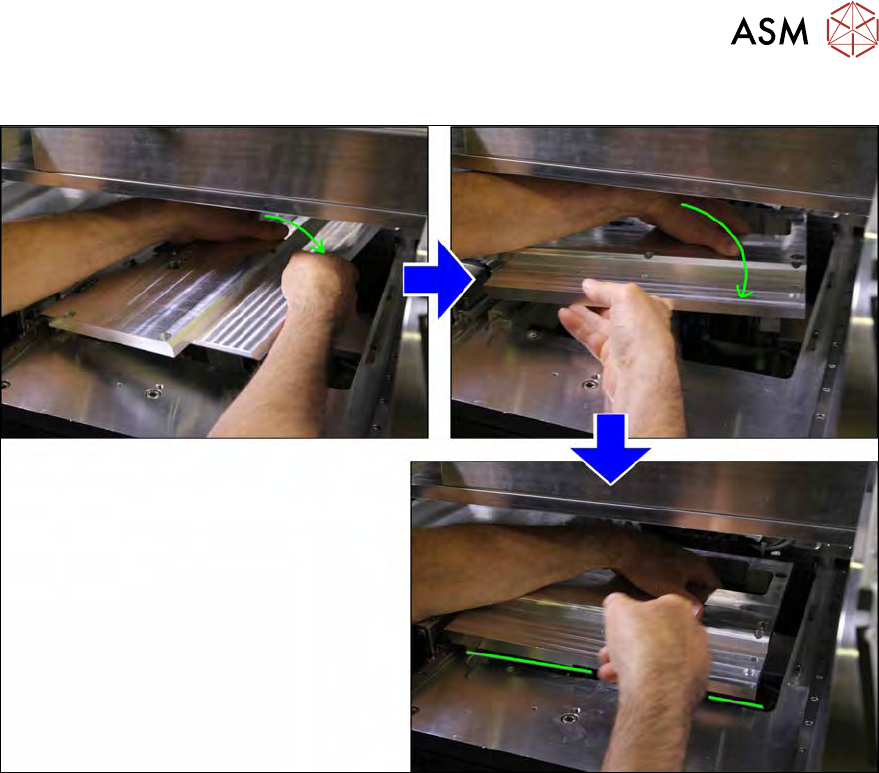
Rotary direction for base plate SWS 2/4
Fig.144:
► Carefully turn the base plate to the right (clockwise), until the plate is parallel to the recess.
7 Die ejector
7.3 Replacing spare parts
128 Service Manual SIPLACE Wafer System (SWS) 11/2018
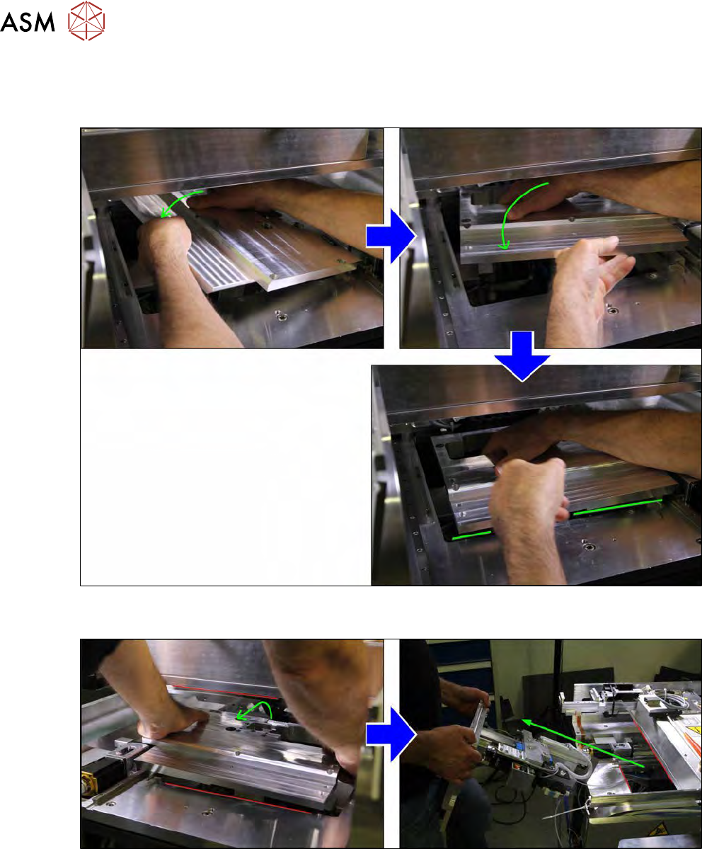
Rotary direction for base plate SWS 1/3
When using a die ejector base plate for an SWS 1/3, the eccentric shaft is to the right of the base
plate when viewed from the direction of the dismantled nozzle changer.
Fig.145:
► Carefully turn the base plate to the left (anticlockwise), until the plate is parallel to the recess.
Fig.146:
► Grasp the base plate by its edge.
Carefully turn the base plate out. Pay attention to the interfering edges (red).
► Carefully pull the base plate out of the SWS.