00195982-03_SM_SWS_EN.pdf - 第146页
7 Die ejector 7.3 Replacing spare parts 146 Service Manual SIPLACE Wafer System (SWS) 11/2018 Fig.180: ► Insert the four screws fastening the base plate. Only tighten these screws slightly to begin with, so that the bas…
7 Die ejector
7.3 Replacing spare parts
Service Manual SIPLACE Wafer System (SWS) 11/2018 145
SWS 1/3
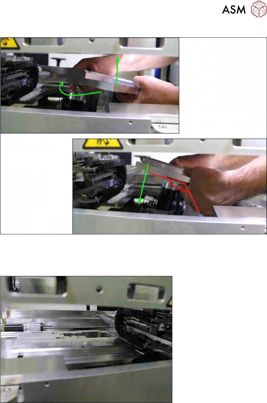
Fig.178:
► Lift the base plate slightly and turn this by approx. 90° to the right (clockwise).
► Carefully lower the base plate.
Fig.179: SWS base plate
7 Die ejector
7.3 Replacing spare parts
146 Service Manual SIPLACE Wafer System (SWS) 11/2018
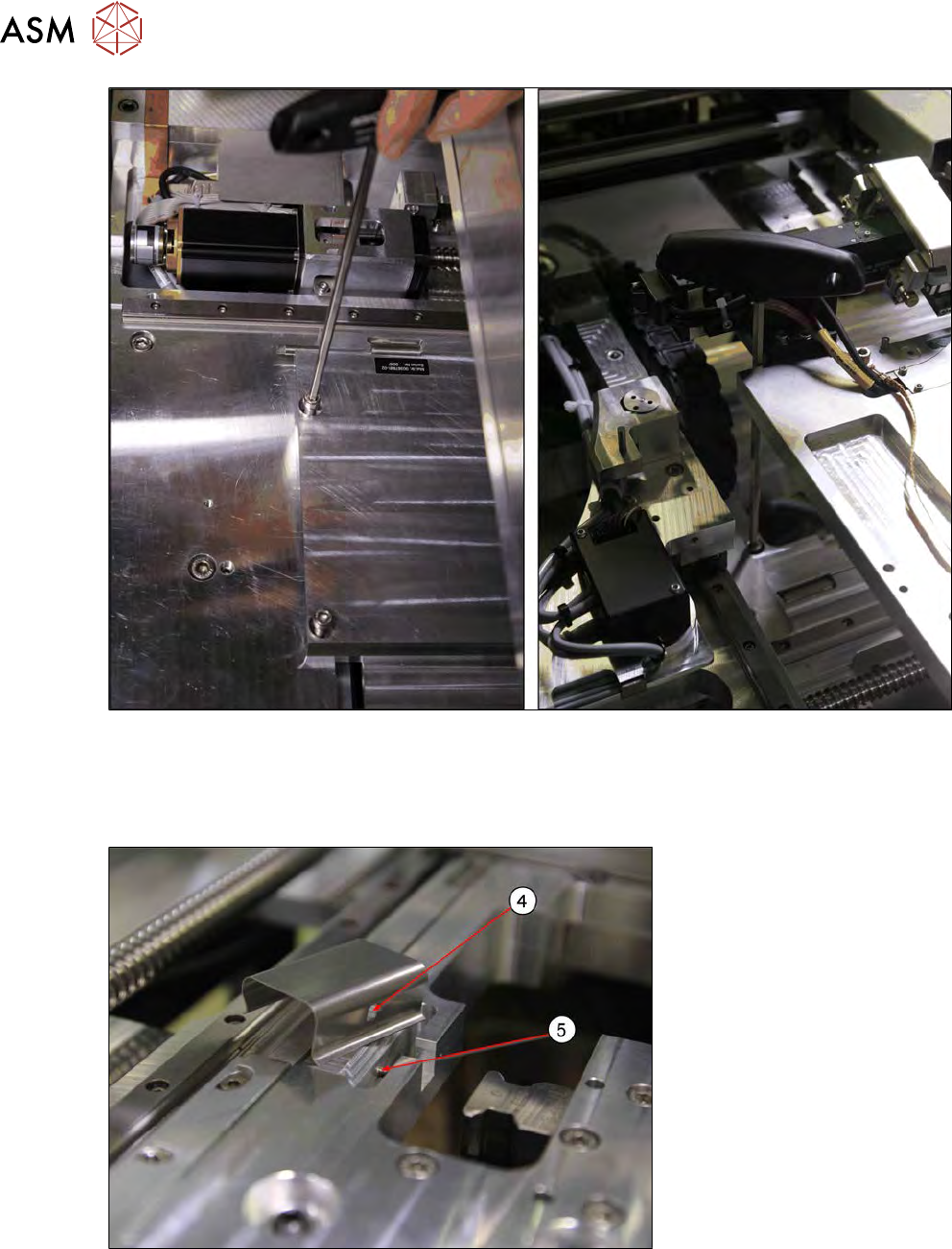
Fig.180:
► Insert the four screws fastening the base plate.
Only tighten these screws slightly to begin with, so that the base plate remains flexible for ad-
justing its alignment.
The two rear screws (towards the wafer lift) are difficult to access.
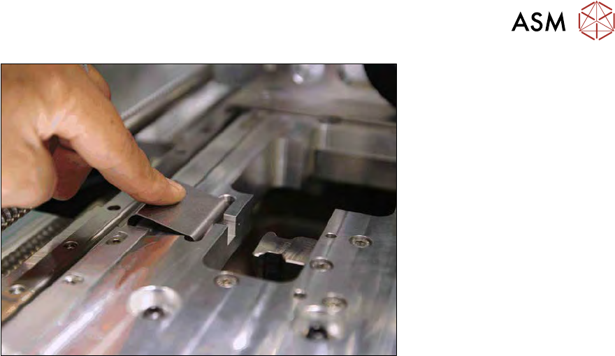
Fig.181:
► Insert the omega spring. The hole (4) drilled in the omega spring is guided onto the holder
pin(5) in the recess.
7 Die ejector
7.4 Mechanical adjustment of the needle position in the X/Y position
Service Manual SIPLACE Wafer System (SWS) 11/2018 147
Fig.182:
► Press the omega spring down until it has engaged completely.
► Then connect all compressed air and vacuum cables plus all cables to the underside of the
die ejector unit (see 7.3.2 "Removing the complete die ejector unit from the SWS" [}122]).
► Reconnect the SWS to the power supply.
7.4 Mechanical adjustment of the needle position in the X/Y
position
Tools
●
T Allen key 5 mm
●
Fork wrench, 5 mm
●
Allen key 3mm, 4mm
Preconditions
●
SWS connected to power supply
7.4.1 Goal for mechanical adjustment of needle position in X/Y direction
The aim is to align the camera center (red cross in the camera image) with the tip of the ejection
system central needle.
In an ideal case, the adjustment and the checking of it should be performed when the SWS is fitted
in the CA machine.
If the adjustment is performed when the SWS is not fitted in the CA machine, there is a risk that the
center point could moved after the SWS has been fitted into the CA machine. Mechanical tension is
the cause for this.
After fitting the SWS into the CA machine, the needle position in relation to the camera center
needs to be checked again and readjusted, if needed.