00195982-03_SM_SWS_EN.pdf - 第124页
7 Die ejector 7.3 Replacing spare parts 124 Service Manual SIPLACE Wafer System (SWS) 11/2018 Fig.138: ► Use a small screwdriver to lever the edge (4) of the omega spring (3) upwards (5) . ► Remove the omega spring up…
7 Die ejector
7.3 Replacing spare parts
Service Manual SIPLACE Wafer System (SWS) 11/2018 123
Procedure
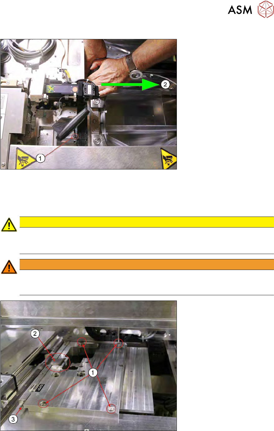
Fig.136:
► In the change position, the wafer table still covers two of the fastening screws(1) for the die
ejector base plate.
You need to manually push the wafer table towards the wafer lift(2), until the screws are ac-
cessible.
CAUTION
Die ejector lowered?
► Before pushing the wafer table, make sure that the die ejector has really been
lowered.
WARNING
Risk of injury to hands
When manually pushing the wafer table, there is always a risk of injury by trapping the
hands.
Fig.137:
► Remove the four screws(1) fastening the die ejector base plate (Allen key5).
The omega spring pulls the base plate against the eccentric shaft(3) X direction. Remove the
omega spring (2) as follows:
7 Die ejector
7.3 Replacing spare parts
124 Service Manual SIPLACE Wafer System (SWS) 11/2018
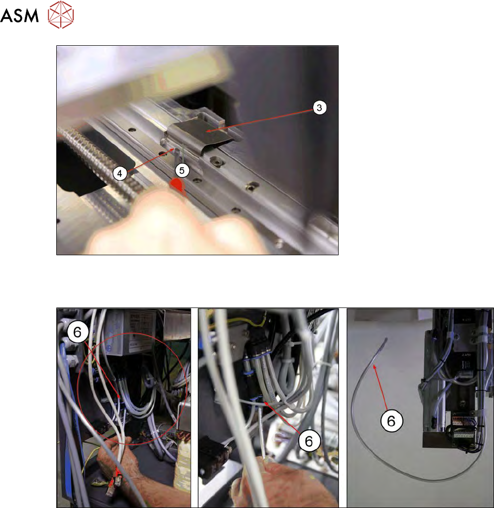
Fig.138:
► Use a small screwdriver to lever the edge(4) of the omega spring (3) upwards(5).
► Remove the omega spring upwards.
Fig.139:
► Pull the compressed air inlet line (6) for the die ejector off the pneumatic distributor.
7 Die ejector
7.3 Replacing spare parts
Service Manual SIPLACE Wafer System (SWS) 11/2018 125
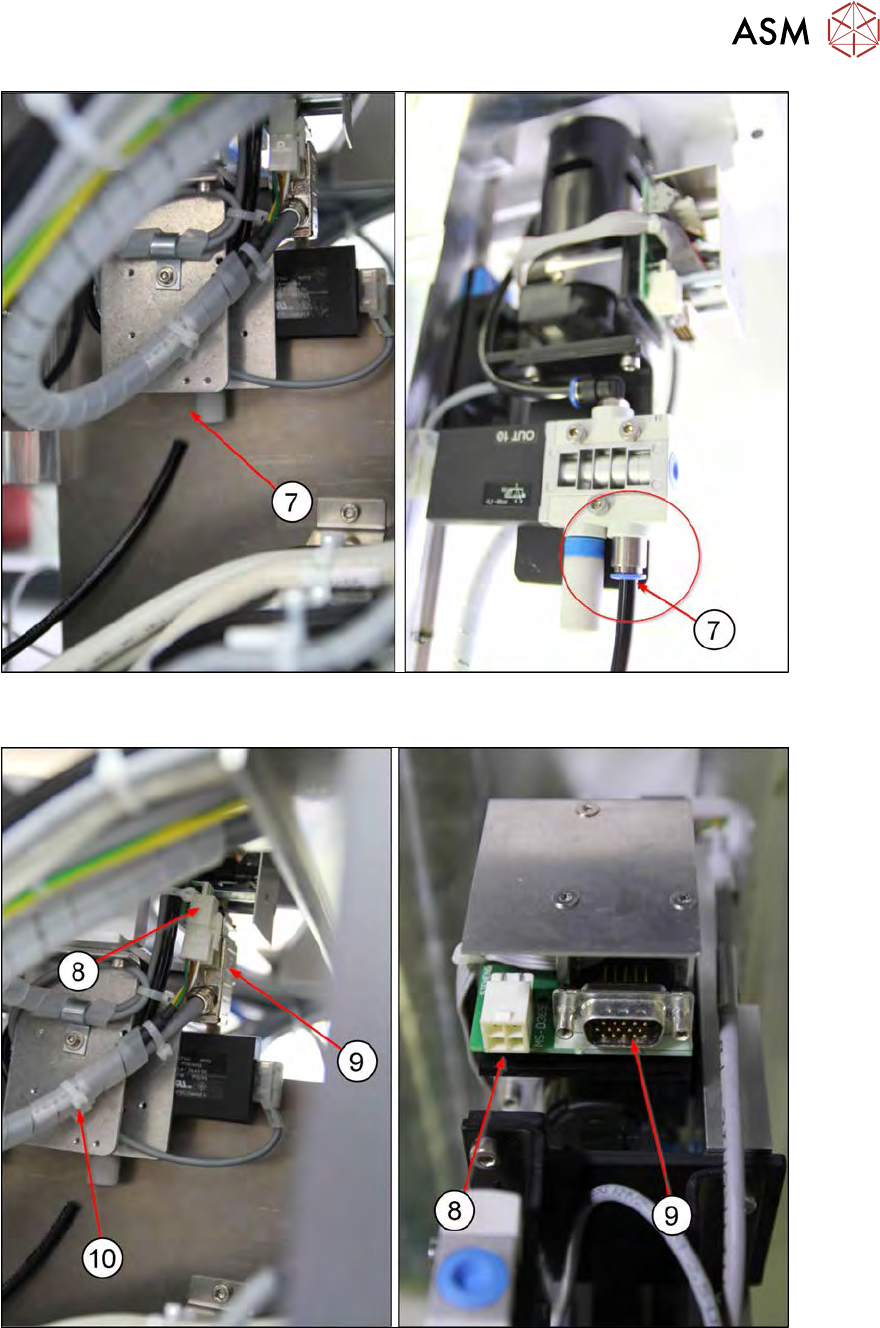
Fig.140:
► Pull the vacuum hose (7) off the vacuum valve of the die ejector.
Fig.141:
► Unplug the following cables:
– (8) Power supply die ejector X4
– (9) Encoder signals die ejector ENC4
– (10) Remove the cable ties