00195982-03_SM_SWS_EN.pdf - 第218页
10 Option Die Attach Unit SWS 10.1 Installing the Option Die Attach Unit SWS 218 Service Manual SIPLACE Wafer System (SWS) 11/2018 Fig.282: Item Designation 1 Pre-wired module assembly Die Attach Unit SWS 2 Voltage supp…
10 Option Die Attach Unit SWS
10.1 Installing the Option Die Attach Unit SWS
Service Manual SIPLACE Wafer System (SWS) 11/2018 217
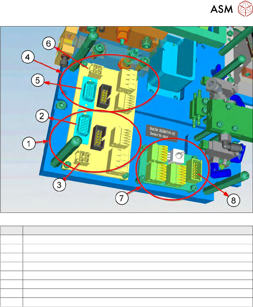
Fig.281:
Item Designation
1 Connecting assembly on board 00379104-xx for Motor M7/Rotate Die Attach
2 Connector ENCH1 for signals Motor Rotate Die Attach to Galil board
3 Connector MOT-1 voltage supply Motor Rotate Die Attach to Galil board
4 Connecting assembly on board 00379104-xx for Motor M8/Flip Tool X to Galil board
5 Connector ENCH2 for signals Motor Flip Tool X to Galil board
6 Connector MOT-2 for voltage supply Motor Flip Tool X to Galil board
7 Connecting assembly on board 00385749-xx for sensors
8 Connector ST1 for sensors to board USB-IO
10 Option Die Attach Unit SWS
10.1 Installing the Option Die Attach Unit SWS
218 Service Manual SIPLACE Wafer System (SWS) 11/2018
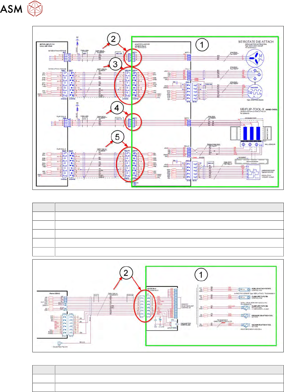
Fig.282:
Item Designation
1 Pre-wired module assembly Die Attach Unit SWS
2 Voltage supply Motor Rotate Die Attach cable 00386236-xx at Connector MOT-1
3 Cable Signals Motor Rotate Die Attach 00386234-xx at Connector ENCH1
4 Cable Power Supply Motor Flip-Tool-X 00386237-xx at Connector MOT-2
5 Cable Signals Motor Flip-Tool-X 00386235-xx at Connector ENCH2
Fig.283:
Item Designation
1 Pre-wired module assembly Die Attach Unit SWS
2 Cable Die Attach Unit Control IO/OUT 00386020-xx at ST1-12
10 Option Die Attach Unit SWS
10.1 Installing the Option Die Attach Unit SWS
Service Manual SIPLACE Wafer System (SWS) 11/2018 219
10.1.3 Installing the Option Die Attach Unit in SWS
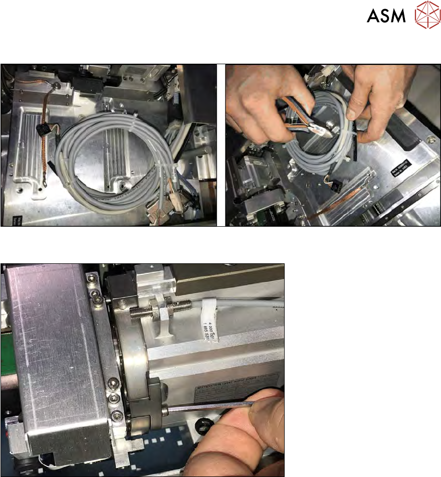
Fig.284:
► Remove the cable ties of the Die Attach cables.
Fig.285:
► Remove the two screws and take out the filling piece on the raceway of the flip head. To pre-
vent any loss of the screws, lay a sheet of paper underneath (not shown in the figure)!
At this position the transfer X axis of the Die Attach Unit is inserted. The transfer X axis moves seg-
ment 1 of the flip head towards the Die Attach segment.