00195982-03_SM_SWS_EN.pdf - 第138页
7 Die ejector 7.3 Replacing spare parts 138 Service Manual SIPLACE Wafer System (SWS) 11/2018 Fig.165: ► All loss prevention locks [03075495-xx] (6) must be in the Flachbohrungen. In order to fix the loss prevention lo…
7 Die ejector
7.3 Replacing spare parts
Service Manual SIPLACE Wafer System (SWS) 11/2018 137
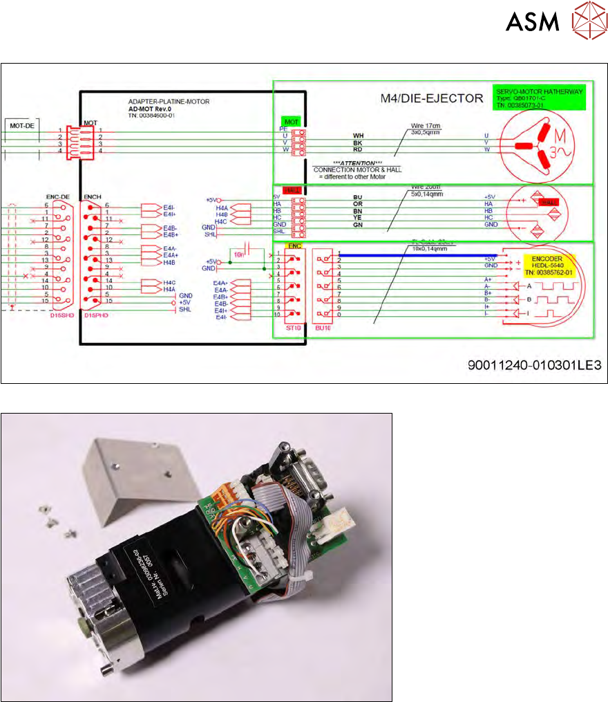
Fig.163:
Fig.164:
► Fit the board cover.
7 Die ejector
7.3 Replacing spare parts
138 Service Manual SIPLACE Wafer System (SWS) 11/2018
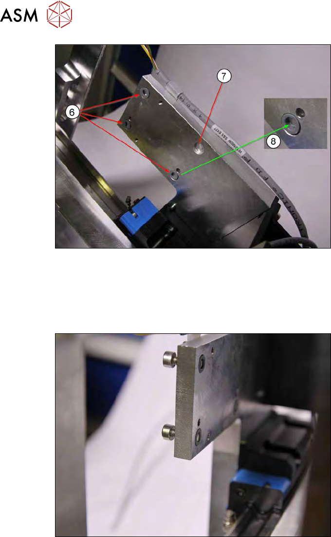
Fig.165:
► All loss prevention locks [03075495-xx](6) must be in the Flachbohrungen.
In order to fix the loss prevention locks into place, you can apply a little Vaseline or similar
grease to the shallow holes(7).
► The thread of the loss prevention locks must be on the inside (towards the shallow hole)(8).
This is the only way to ensure that the screws have approx. 2mm secure hold.
Fig.166:
It is possible that the screws may still be in the loss prevention lock after dismantling.
► Tighten all screws so that they are level with the assembly surface (see diagram).
7 Die ejector
7.3 Replacing spare parts
Service Manual SIPLACE Wafer System (SWS) 11/2018 139
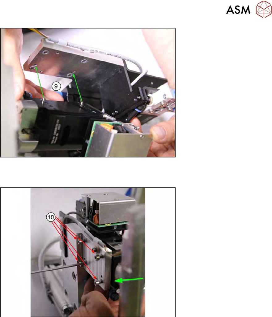
Fig.167:
► Position the Z axis die ejector on the support plate, with its two pins in the corresponding
holes of the support plate(9).
Fig.168:
► Press the Z axis die ejector against the carrier and tighten the four fastening screws(10) an.
► If not already done, now remove the fork light barrier from the Z axis die ejector.