00195982-03_SM_SWS_EN.pdf - 第129页
7 Die ejector 7.3 Replacing spare parts Service Manual SIPLACE Wafer System (SWS) 11/2018 129 Fig.147: ► Place the die ejector unit down on the base plate. 7.3.3 Removing the Z axis from the die ejector Fig.148: ► Plac…
7 Die ejector
7.3 Replacing spare parts
128 Service Manual SIPLACE Wafer System (SWS) 11/2018
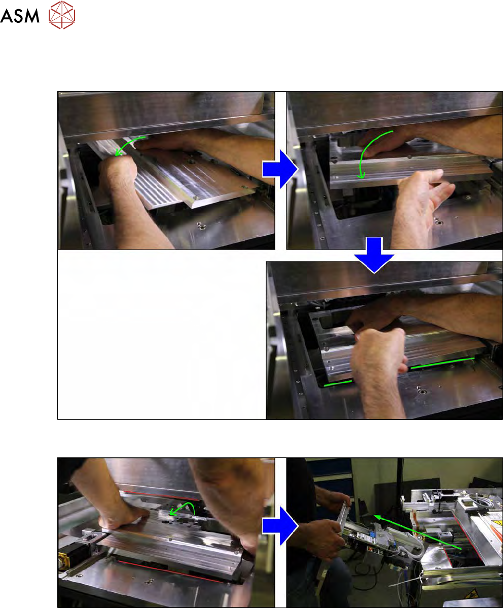
Rotary direction for base plate SWS 1/3
When using a die ejector base plate for an SWS 1/3, the eccentric shaft is to the right of the base
plate when viewed from the direction of the dismantled nozzle changer.
Fig.145:
► Carefully turn the base plate to the left (anticlockwise), until the plate is parallel to the recess.
Fig.146:
► Grasp the base plate by its edge.
Carefully turn the base plate out. Pay attention to the interfering edges (red).
► Carefully pull the base plate out of the SWS.
7 Die ejector
7.3 Replacing spare parts
Service Manual SIPLACE Wafer System (SWS) 11/2018 129
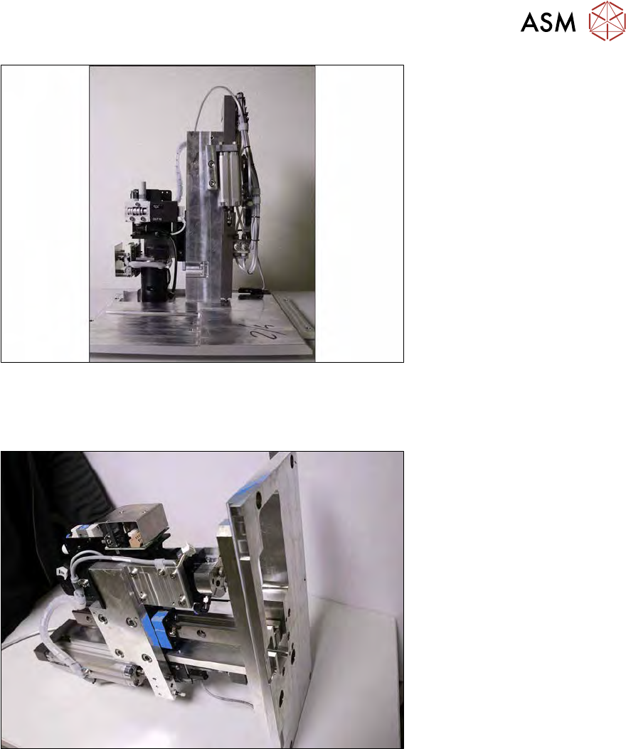
Fig.147:
► Place the die ejector unit down on the base plate.
7.3.3 Removing the Z axis from the die ejector
Fig.148:
► Place the die ejector unit down on its side, as shown in the diagram.
7 Die ejector
7.3 Replacing spare parts
130 Service Manual SIPLACE Wafer System (SWS) 11/2018
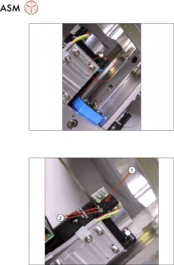
Fig.149:
► Pull the vacuum hose off.
You now need to dismantle the fork light barrier board. To do so, proceed as follows:
Fig.150:
► Remove the two screws(2) (Allen key 2.5) and then take off the fork light barrier (1).