00195982-03_SM_SWS_EN.pdf - 第119页
7 Die ejector 7.1 Overview of main assemblies Service Manual SIPLACE Wafer System (SWS) 11/2018 119 7 Die ejector According to the location there are two different variants that only differ in their mirrored arrange- men…
6 Supply unit
6.3 Settings
118 Service Manual SIPLACE Wafer System (SWS) 11/2018
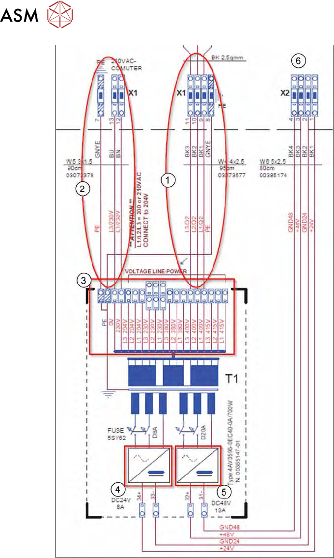
Fig.131: Connection input for transformer
1. Power input from terminal panel X1
2. Output PC
3. Terminal block input voltage for transformer
4. Fuse 24V
5. Fuse 48V
6. Output voltage to terminal panel X2
► Connect the pneumatic hoses to the manometer (observe assignment).
► Fit the side and front covers.
► Fit the SWS into the machine.
7 Die ejector
7.1 Overview of main assemblies
Service Manual SIPLACE Wafer System (SWS) 11/2018 119
7 Die ejector
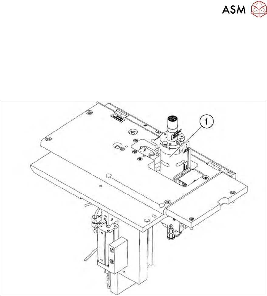
According to the location there are two different variants that only differ in their mirrored arrange-
ment of the modules.
●
Die ejector SWS12 (1/3) [00387913-xx]
●
Die ejector SWS12 (2/4) [00387881-xx]
7.1 Overview of main assemblies
Fig.132: Main die ejector assemblies
1. Z axis die ejector
7 Die ejector
7.2 Overview of spare parts
120 Service Manual SIPLACE Wafer System (SWS) 11/2018
7.2 Overview of spare parts
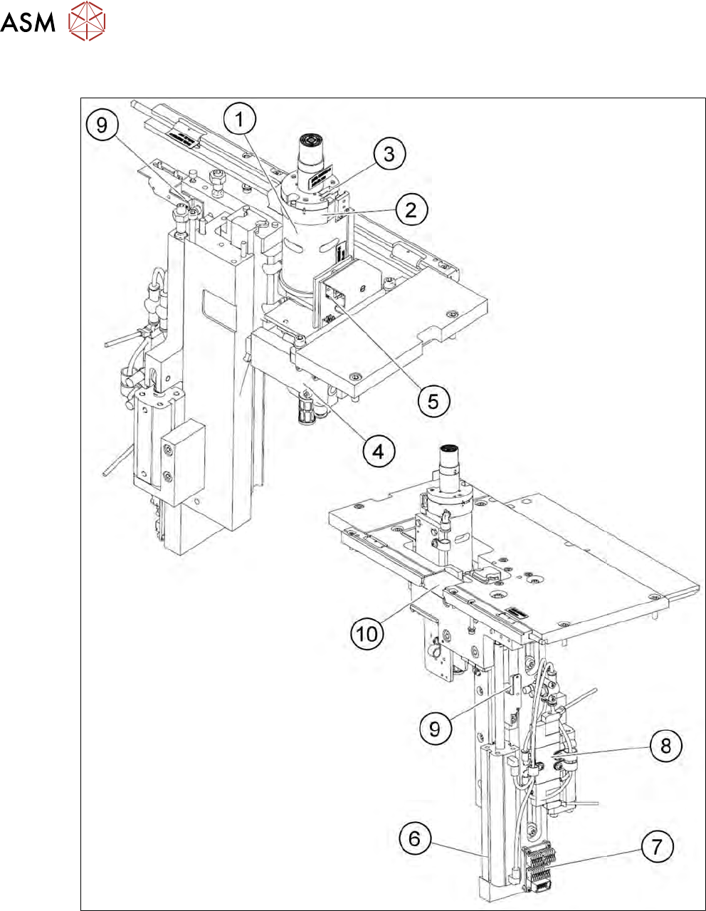
Fig.133: Die ejector from front and back