00195982-03_SM_SWS_EN.pdf - 第89页
5 Basic frame – X/Y unit 5.3 Replacing parts Service Manual SIPLACE Wafer System (SWS) 11/2018 89 Fig.81: ► Move the wafer table until the X motor is level with the semicircular recess in the side frame. Fig.82: ► Now …
5 Basic frame – X/Y unit
5.3 Replacing parts
88 Service Manual SIPLACE Wafer System (SWS) 11/2018
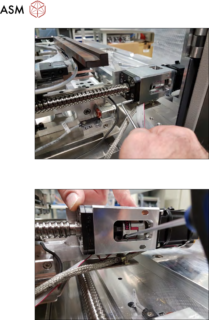
Fig.79:
► Remove the four Allen key fastening screws (not the Phillips screws) from the coupling plate,
together with the spindle plate.
Fig.80:
► Remove the two clamping screws from the coupling.
5 Basic frame – X/Y unit
5.3 Replacing parts
Service Manual SIPLACE Wafer System (SWS) 11/2018 89
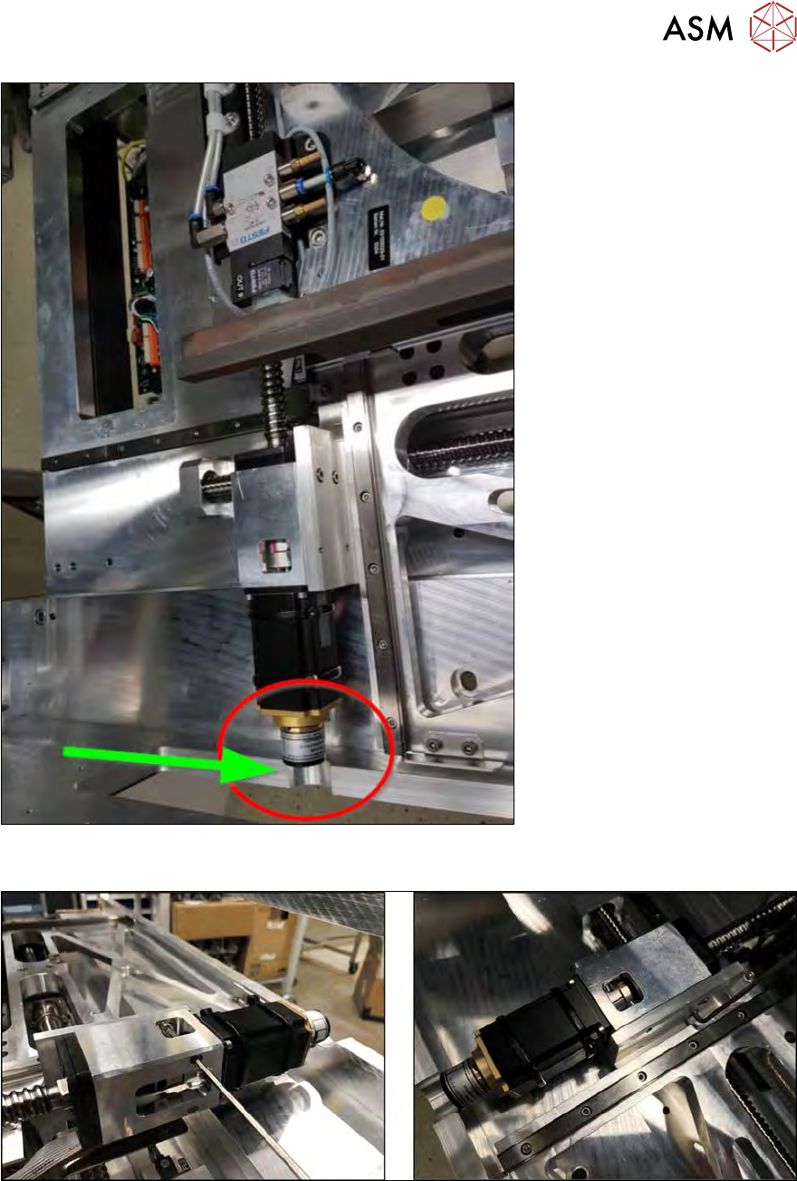
Fig.81:
► Move the wafer table until the X motor is level with the semicircular recess in the side frame.
Fig.82:
► Now remove the two screws fastening the front of the coupling housing.
► Remove the two fastening screws on the back with a short (modified) Allen key.
5 Basic frame – X/Y unit
5.3 Replacing parts
90 Service Manual SIPLACE Wafer System (SWS) 11/2018
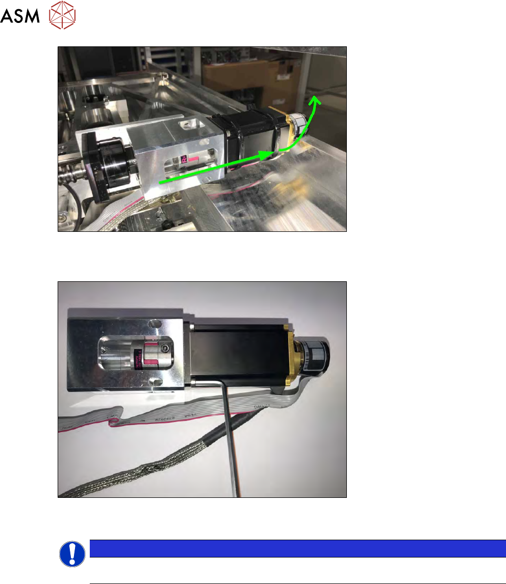
Fig.83:
► Pull the X motor, together with the coupling plate, away towards the back and lift the unit up
and out!
Fig.84:
► Remove the four screws fastening the motor.
NOTICE
You do not necessarily need to remove the cable ties fixing the motor cable to the motor
housing.