00195982-03_SM_SWS_EN.pdf - 第491页
18 Appendix 18.4 Control system IN/OUT Service Manual SIPLACE Wafer System (SWS) 11/2018 491 Adapter board AD-WT Rev.0 (229 x 65 mm), installation location: table plate for wafer table Connections for: ● 21x feed-through…

18 Appendix
18.4 Control system IN/OUT
490 Service Manual SIPLACE Wafer System (SWS) 11/2018
18.4 Control system IN/OUT
18.4.1 Control boards input/output
DMC1886(1866) Galil motion controller (PCI bus) with integrated I/O system
Connections via 2x 100 pin connector:
●
16x digital input, optoisolation, 24V/PNP,
●
8x digital input 5V/NPN,
●
8x analog input +/-10V, (not used)
●
16x digital output, optoisolation 24V/500mA, p-switching
DMC1826 Galil motion controller (PCI bus) with integrated I/O system
Connections via 1x 100 pin connector for:
●
8x digital input, optoisolation, 24V/PNP,
●
8x analog input +/-10V, (not used)
●
8x digital output, optoisolation 24V/500mA, p-switching
Distributor I/O board DMC-INT1 (145 x 72mm), installation point: wafer lift
Connection terminals for:
●
8x digital input 24VPNP with red LED display.
●
8x digital output 24V / max2A / p-switching with yellow LED display.
●
12x digital input 24V/PNP, = limit and home sensors for 4 motors, with LED.
●
4x terminal MCMx (motor command), 4x terminal AENx (amplify enable) with LED.
●
1x ABORT (cancel), 1x ECC (encoder common), 1x INC (input common).
●
1x LSC (limit common), 8x analog input +/-10V, 4x terminals for analog GND.
●
16x terminal (gray) GND, 12x terminal (orange) 24V, with fuse F1/4AT.
●
Terminals (orange) 2x 5V, 1x +12V, 1x -12V, from PC.
Distributor I/O board DMC-INT2 (230 x 145mm) installation point: electrical unit
Connection terminals for:
●
24x digital input 24V/PNP with red LED display.
●
16x digital output / 24V / max2A / p-switching / with yellow LED display.
●
24x digital input 24V/PNP, limit and home sensors for 8 motors, with red LED.
●
8x terminal MCMx (motor command), 8x terminal AENx (amplify enable) with LED.
●
2x ABORT (cancel), 2x ECC (encoder common), 2x INC (input common).
●
2x LSC (limit common), 8x analog input +/-10V, 4x terminals for analog GND.
●
40x terminal (blue) GND, 24x terminal 24V (orange), with fuse F1/4AT.
●
Terminals (orange) 2x 5V (via F2/1AT), 2x +12V, 2x -12V, from PC.
18 Appendix
18.4 Control system IN/OUT
Service Manual SIPLACE Wafer System (SWS) 11/2018 491
Adapter board AD-WT Rev.0 (229 x 65 mm), installation location: table plate for
wafer table
Connections for:
●
21x feed-through terminals for in/outputs
●
12x feed-through terminals for home and limit sensors, (for servo motor 1-4)
●
15x terminals (orange) 24V, secured via F1/2AT, control LED1 green.
●
15x terminals (gray) GND.
●
1x fuse for 5V logic voltage, F2/0.5AF, control LED2 green.
●
Integrated logic control for the wafer table limit cutoff, which protects the die ejector, with
jumper J1/2/3/4/5 for logic setting.
●
2x stepping motor control for X/Y axis die ejector, = option.
●
1x feed-through terminals for a servo motor, Hall sensors and encoder
18.4.2 Structure of DMC-18x6 I/O system
The complete input/output system is integrated into the Galil motion controllers 1x "DMC1886" or
"DMC1866" and "DMC1826".
The signal line is run via 3 100 pin cables, from the Galil DMC18x6 and is looped through via three
"AMP-19540"(19520") amplifiers.
At the amplifier, the signals are transmitted via the "AUX-IO J3x" (44 pin) connector to the "DMC-
INT2" or "DMC-INT1" board.
The analog input and the digital input 5V are each transmitted via the 15 pin "analog 1" connector
to the amplifier on the "DMC-INT2" board.
At the "DMC-INT1(2)" boards, the signals are picked off from the terminal connections and either
directly distributed in the machine or distributed via the connection cable with sub-D connector.
The inputs on the "DMC18x6" can be operated either with NPN or PNP.
The joint "INCOM" connection for the inputs to the "DMC18x6" is run via the "DMC-INT1(2)" adap-
ter board with jumper "J2(J4)" to COM24, so that the inputs use PNP logic.
Label DMC1886(66) Input 1 to 24 = IN1, IN2,…IN24
Analog input 1 to 8 = ANA1, ANA2,…ANA3
Output 1 to 16 = OUT1, OUT2,…OUT16
Label DMC1826 Input 1 to 8 = IN1.1, IN1.2,…IN1.8
Output 1 to 8 = OUT1.1, OUT1.2,…OUT1.8
Label USB-IO Input-1 to 8 = DI1, DI2,…DI8
Analog input 1 to 8 = AI1, AI2,…AI3
Output-1 to 8 = DO1, DO2,…DO8
Current output (current control) 1 to 8 = ILED1, ILED2,…ILED8
18 Appendix
18.4 Control system IN/OUT
492 Service Manual SIPLACE Wafer System (SWS) 11/2018
18.4.2.1 Signal tracking DMC-18x6
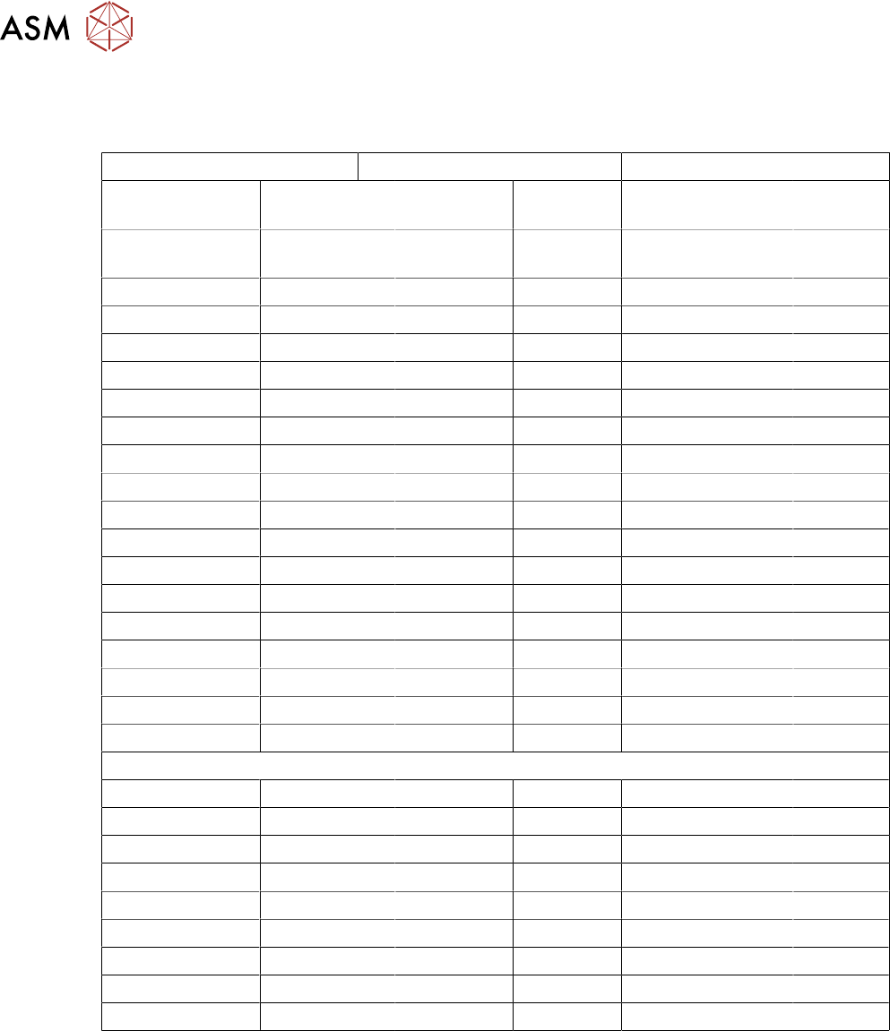
Input/output DMC-1886(1866)
PCI - DMC1886(66) Amplifier 1 AMP19540 Adapter board DMC-INT2
"AXIS 1-4" Cable 100 pin "J1 axis1-4" "J31 AUX-
IO"
Cable 44 pin " X1"
Connector 100
pin.
Connector
100 pin.
Connector
44 pin.
Connector 44 pin. Terminals
Pin69 = LSCOM Pin69 Pin44 Pin44 -- J1 INC-X1 INC-X1
Pin70 = IN1 Pin70 Pin24 Pin24 IN1
Pin71 = IN2 Pin71 Pin38 Pin38 IN2
Pin72 = IN3 Pin72 Pin 8 Pin 8 IN3
Pin73 = IN4 Pin73 Pin25 Pin25 IN4
Pin74 = IN5 Pin74 Pin39 Pin39 IN5
Pin75 = IN6 Pin75 Pin9 Pin9 IN6
Pin76 = IN7 Pin76 Pin26 Pin26 IN7
Pin77 = IN8 Pin77 Pin40 Pin40 IN8
Pin79 = OUT1 Pin79 Pin20 Pin20 OUT1
Pin80 = OUT2 Pin80 Pin 5 Pin 5 OUT2
Pin81 = OUT3 Pin81 Pin21 Pin21 OUT3
Pin82 = OUT4 Pin82 Pin19 Pin19 OUT4
Pin83 = OUT5 Pin83 Pin4 Pin4 OUT1
Pin84 = OUT6 Pin84 Pin2 Pin2 OUT2
Pin85 = OUT7 Pin85 Pin18 Pin18 OUT3
Pin86 = OUT8 Pin86 Pin3 Pin3 OUT4
"ANALOG-1" X 15 pin cable 15 pin "X2"
Pin 1 = AGND Pin 1 Pin1/9 Pin1/9 AGND
Pin91 = ANA1 Pin91 Pin 2 Pin 2 ANA1
Pin92 = ANA2 Pin92 Pin10 Pin10 ANA2
Pin93 = ANA1 Pin93 Pin 3 Pin 3 ANA3
Pin94 = ANA2 Pin94 Pin11 Pin11 ANA4
Pin91 = ANA1 Pin91 Pin 2 Pin 2 ANA1
Pin92 = ANA2 Pin92 Pin10 Pin10 ANA2
Pin93 = ANA1 Pin93 Pin 3 Pin 3 ANA3
Pin94 = ANA2 Pin94 Pin11 Pin11 ANA4