00195982-03_SM_SWS_EN.pdf - 第34页
2 Overview of the SIPLACE wafer system (SWS) 2.4 Description of SWS assemblies 34 Service Manual SIPLACE Wafer System (SWS) 11/2018 Fig.15: Die ejector basic unit 1. Z axis 2. Z axis movement (pneumatic)
2 Overview of the SIPLACE wafer system (SWS)
2.4 Description of SWS assemblies
Service Manual SIPLACE Wafer System (SWS) 11/2018 33
2.4.1.4 Die ejector
According to the location (2/4 or 1/3) there are two different variants that only differ in their mirrored
arrangement of the modules.
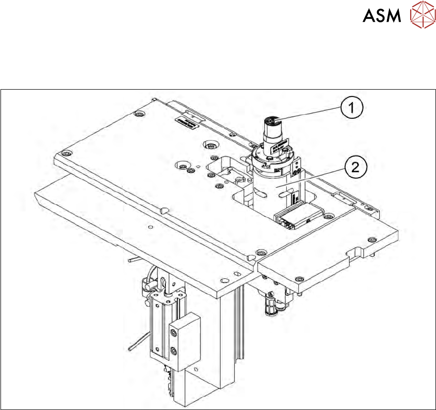
Fig.14: Main die ejector assemblies
1. Ejector tool
2. Z axis
2 Overview of the SIPLACE wafer system (SWS)
2.4 Description of SWS assemblies
34 Service Manual SIPLACE Wafer System (SWS) 11/2018
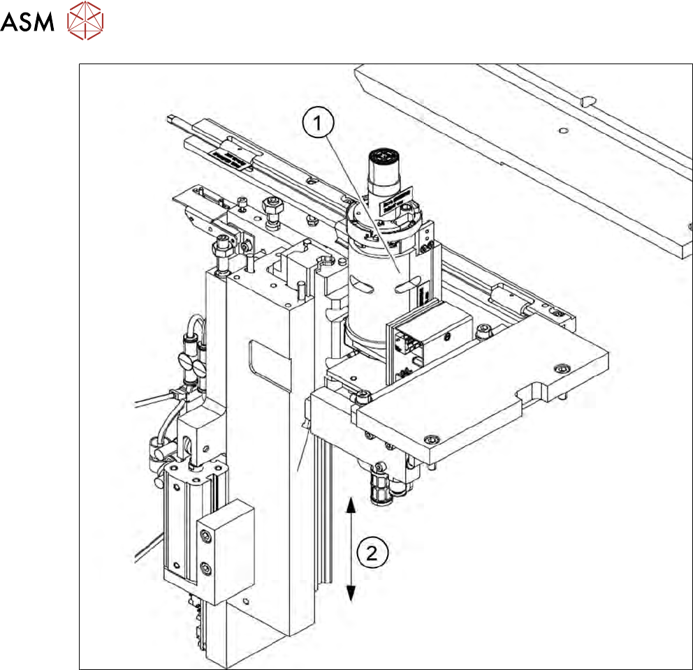
Fig.15: Die ejector basic unit
1. Z axis
2. Z axis movement (pneumatic)
2 Overview of the SIPLACE wafer system (SWS)
2.4 Description of SWS assemblies
Service Manual SIPLACE Wafer System (SWS) 11/2018 35
2.4.1.5 Die ejector
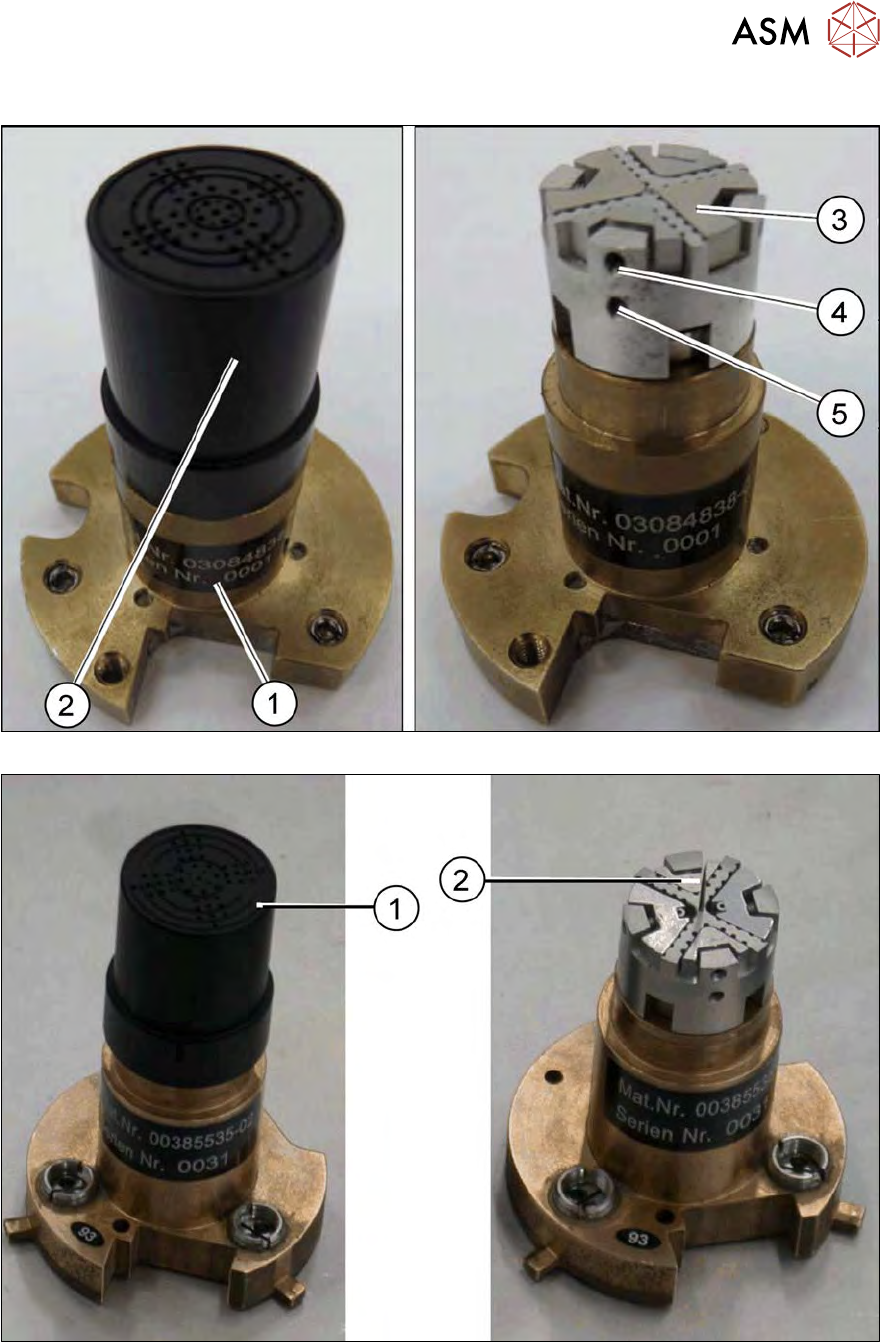
Fig.16: Ejector tool with magnetic table (new)
Fig.17: Ejector tool with bayonet lock (old)
1. Vacuum cap
2. Ejector needle
The die ejector is used to release the die from the wafer foil. It consists of a
basic unit and the ejector tool.