00195982-03_SM_SWS_EN.pdf - 第142页
7 Die ejector 7.3 Replacing spare parts 142 Service Manual SIPLACE Wafer System (SWS) 11/2018 7.3.5 Fitting the complete die ejector unit into the SWS Preconditions ● SWS removed from machine ● SWS disconnected from the …
7 Die ejector
7.3 Replacing spare parts
Service Manual SIPLACE Wafer System (SWS) 11/2018 141
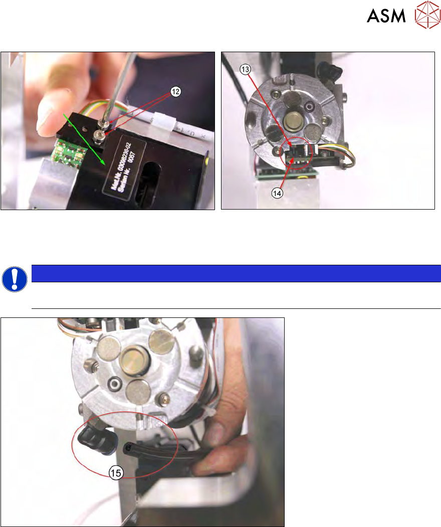
Fig.171:
► Press the fork light barrier "into the corner" (downwards and forwards) and screw into
place(12).
NOTICE
► Make sure that the switch flag of the Z axis die ejector(13) is between the fork light
barriers(14).
Fig.172:
► Connect the vacuum hose(15).
7 Die ejector
7.3 Replacing spare parts
142 Service Manual SIPLACE Wafer System (SWS) 11/2018
7.3.5 Fitting the complete die ejector unit into the SWS
Preconditions
●
SWS removed from machine
●
SWS disconnected from the power supply
Procedure
To fit the complete die ejector unit into the SWS, follow the removal instructions in reverse order
(see 7.3.2 "Removing the complete die ejector unit from the SWS" [}122]).
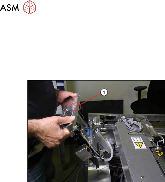
Fig.173:
► Insert the base plate into the SWS. Make sure that the recess for the omega spring(1) is al-
ways at the front.
7 Die ejector
7.3 Replacing spare parts
Service Manual SIPLACE Wafer System (SWS) 11/2018 143
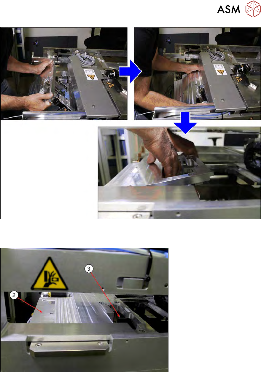
Fig.174:
► Thread the base plate in and position it on the SWS plate. Make sure that it does not bump
against anything.
Fig.175:
► Place the base plate down on the SWS plate (2). The die ejector recess (3) points in the direc-
tion of the wafer lift.