00195982-03_SM_SWS_EN.pdf - 第157页
7 Die ejector 7.5 Mechanical adjustment of the die ejector unit in the Z direction (focus) Service Manual SIPLACE Wafer System (SWS) 11/2018 157 Fig.200: Diagram of the needle position (example) ● Ejection system, 5 nee…
7 Die ejector
7.5 Mechanical adjustment of the die ejector unit in the Z direction (focus)
156 Service Manual SIPLACE Wafer System (SWS) 11/2018
7.5.1.1 Preparatory tasks
► Move the wafer table to the change position.
► Move the die ejector upwards.
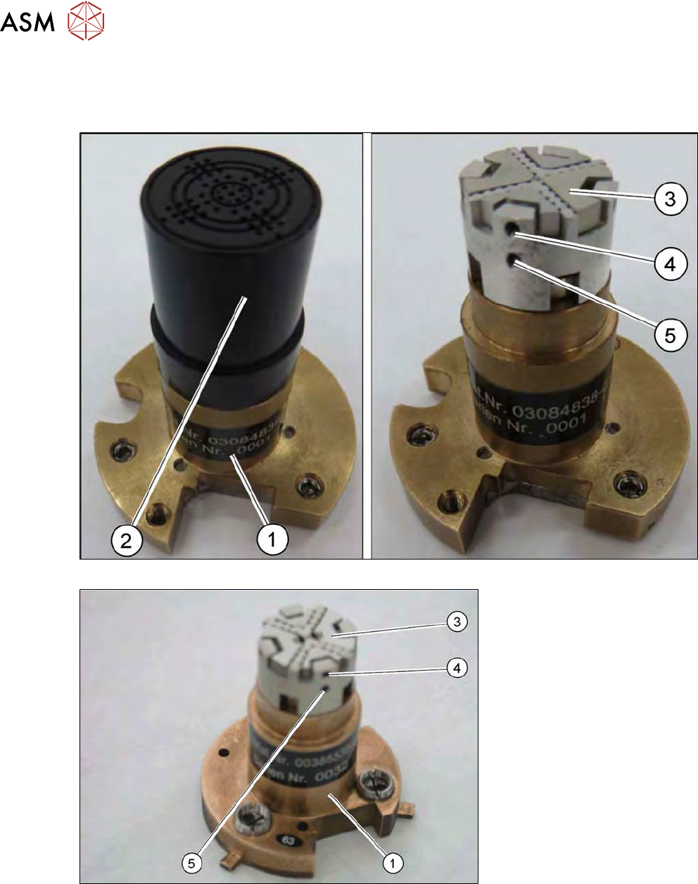
Fig.198: Needle unit for die ejector, magnetic
Fig.199: Needle unit for the die ejector with bayonet fastening (if still used)
► Twist the needle unit (1) off the lock.
► Pull the black cap (2) off. The needles (3) are located under the cap.
ð The needles are clamped in four sectors. One needle is in the center.
► The grub screws (4) at the four segments clamp the needles into place in the needle unit.
The center needle is held in placed by the bottom grub screw (5).
7 Die ejector
7.5 Mechanical adjustment of the die ejector unit in the Z direction (focus)
Service Manual SIPLACE Wafer System (SWS) 11/2018 157
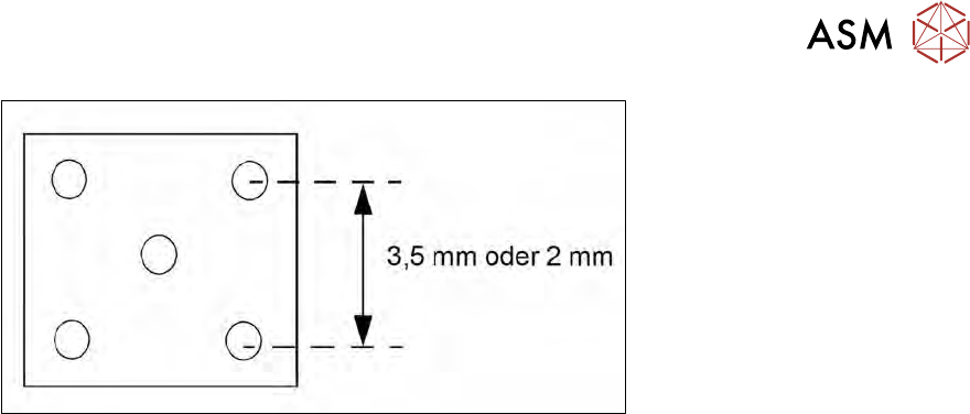
Fig.200: Diagram of the needle position (example)
●
Ejection system, 5 needles with 3.5 mm spacing [00385535-xx]
●
Ejection system, 5 needles with 2 mm spacing [00386908-xx]
► The 2x2mm needle kit requires a central needle fixture with a threaded pin 2x2mm, tightened
with a torque of 10Ncm.
► Depending on the application, fit the relevant needles into the openings in the four segments.
7 Die ejector
7.5 Mechanical adjustment of the die ejector unit in the Z direction (focus)
158 Service Manual SIPLACE Wafer System (SWS) 11/2018
7.5.1.2 Setting the needles with the calibration standard [03098221-xx] (for die ejector,
magnetic)
Tools
●
Needles (wear part)
●
Calibration standard for die ejector, magnetic [03098221-xx]
The needles are all set at a defined height and common level with the help of the calibration
standard for the die ejector.
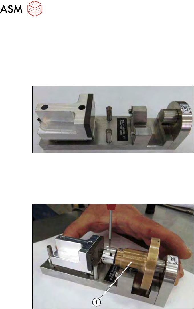
Fig.201: Calibration standard for die ejector, magnetic [03098221-xx]
Procedure
► Remove the black cap on the needle unit.
► Carefully insert all needles into the segments and align the needles roughly in one line.
► Loosely tighten the grub screws. You must still be able to move the needles.
Fig.202: Calibration standard for die ejector, magnetic
► Place the needle unit into the calibration standard for the die ejector (1).
► Place the ejection part into the device. The central bolt of this device must be against the ejec-
tion plunger and the bronze part must be flexibly against the radius nib.
► Turn the ejection part (bronze) into the required position.
► Press the bronze part slightly down into the prisms of the device.
► Push the ejection needles into the required holes (the threaded pin must be released).
► Move the spring-back adjusting slide in the direction of the stop bolt and hold it in place.
► Push the ejection needles in the direction of the setting surface (use tweezers) and pull the
ejection needle tightly into place with the threaded pins (torque 0.1Nm).