00195982-03_SM_SWS_EN.pdf - 第133页
7 Die ejector 7.3 Replacing spare parts Service Manual SIPLACE Wafer System (SWS) 11/2018 133 Fig.155: Pulling off Fig.156: Dismantled Z axis die ejector ► Pull off the Z axis die ejector. Make sure that the four loss …
7 Die ejector
7.3 Replacing spare parts
132 Service Manual SIPLACE Wafer System (SWS) 11/2018
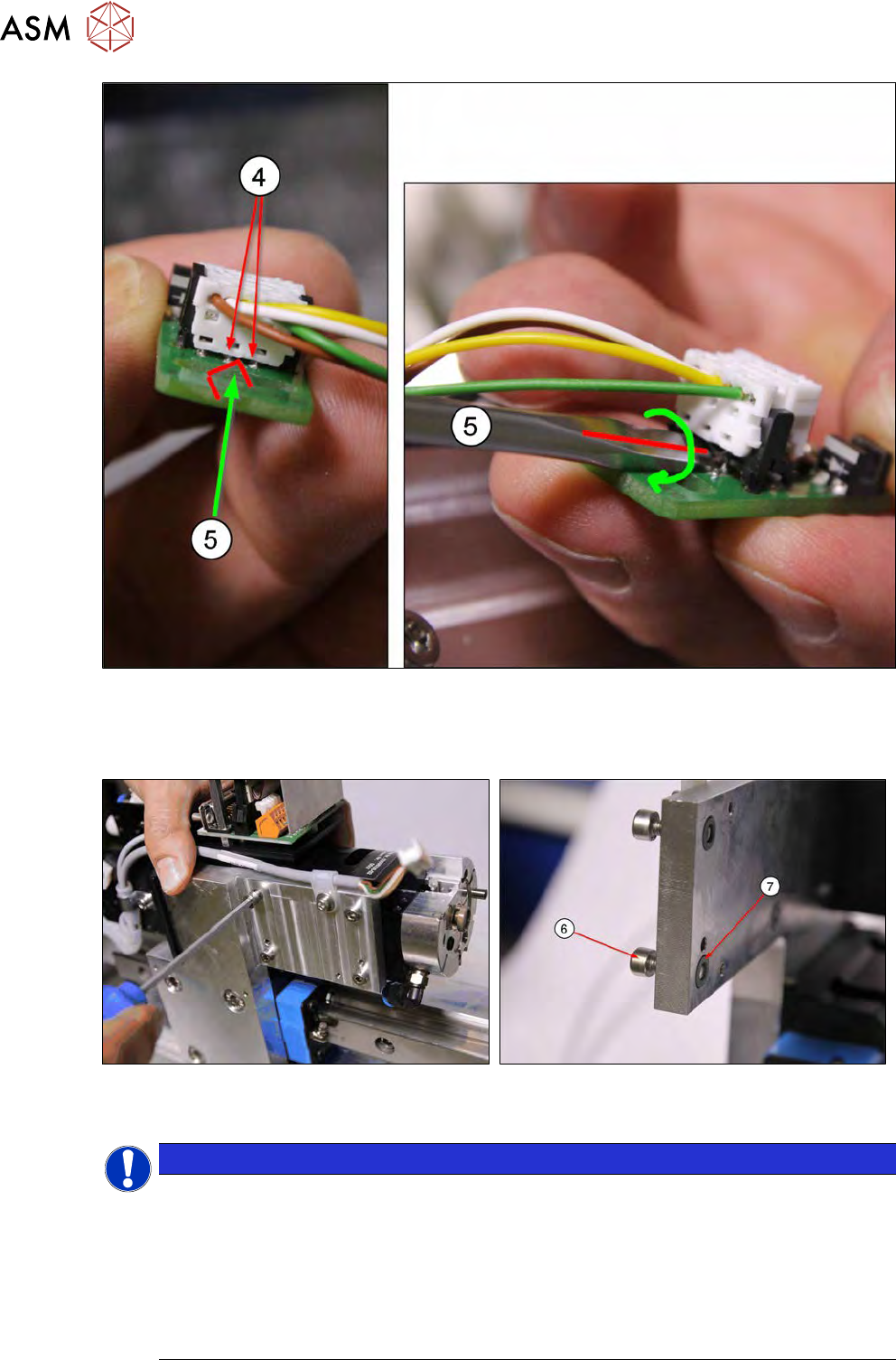
Fig.153:
► Option 2: Push the tip of a screwdriver (5) sideways between the two connection pins on the
connector(4).
Turn slightly to lever the connector out of the holder.
Fig.154:
► Loosen the four screws fastening the Z axis die ejector.
NOTICE
The four fastening screws (6) each have a loss prevention lock [03075495‑xx](7). This loss
prevention lock is located between the support plate and the Z axis die ejector, in a shallow
sink. The fastening screws(6) do not need to be completely removed as they can be held
by the last turns of the thread in the loss prevention lock(7).
The lock thread is at the base of the shallow sink, meaning that there is about 2 mm lock
thread before the screw could fall out.
► However, if the screws are removed completely, make sure that these loss prevention
locks are not lost when the Z axis die ejector is removed.
7 Die ejector
7.3 Replacing spare parts
Service Manual SIPLACE Wafer System (SWS) 11/2018 133
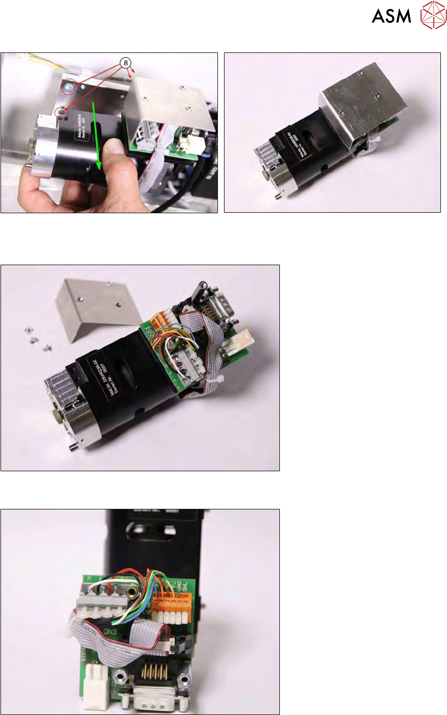
Fig.155: Pulling off
Fig.156: Dismantled Z axis die ejector
► Pull off the Z axis die ejector. Make sure that the four loss prevention locks (8) do not fall out
(diagram shows two visible and two covered).
Fig.157:
► Remove the board cover.
Fig.158:
► Disconnect all cables (small screwdriver).
► Disconnect the encoder signal (ENC).
7 Die ejector
7.3 Replacing spare parts
134 Service Manual SIPLACE Wafer System (SWS) 11/2018
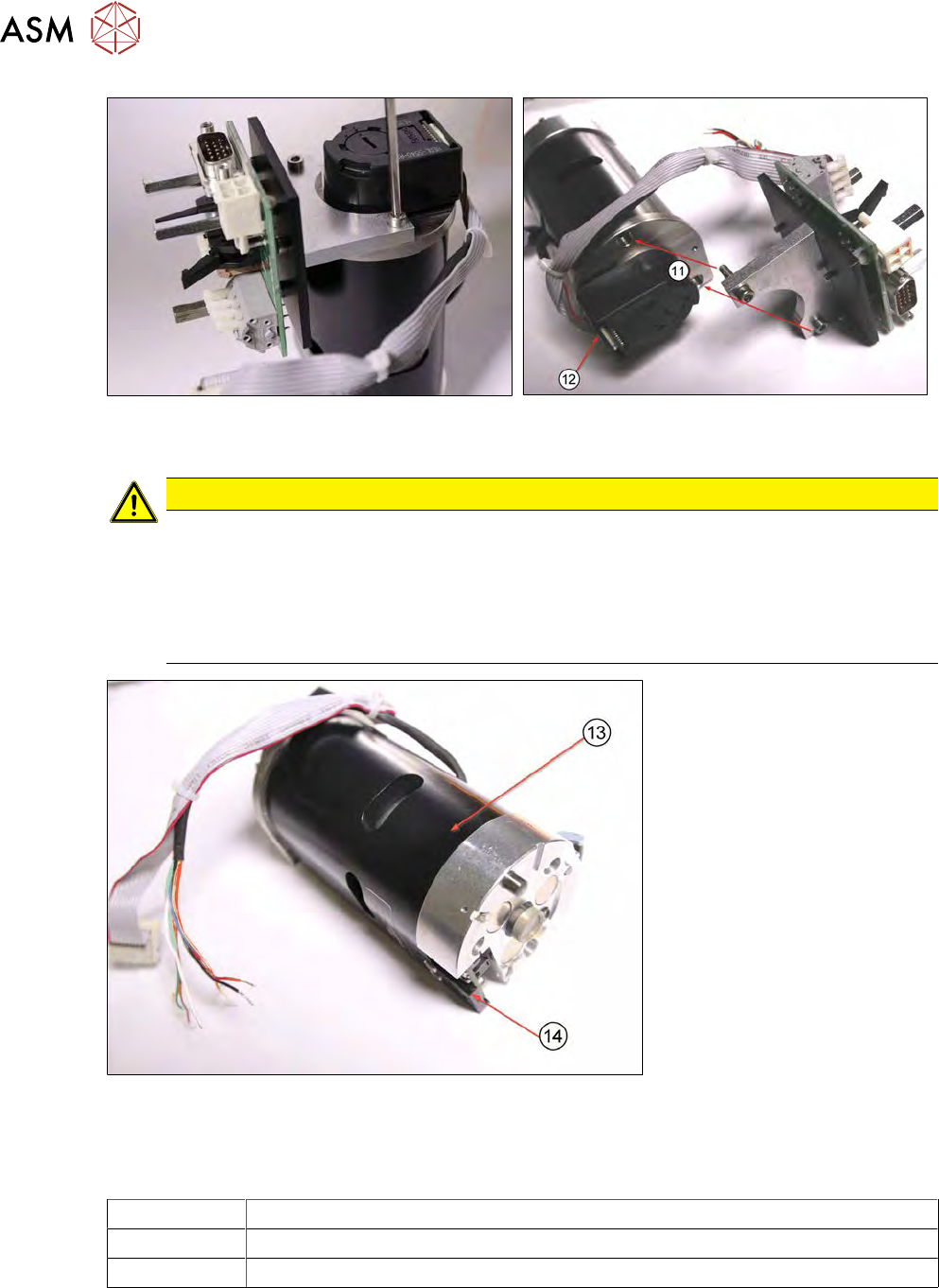
Fig.159:
► Remove the board holder from the motor.
CAUTION
Screws
► Make sure that the two screws (M3x14) for fastening the board holder(11) are longer
than the covered third screw(12) on the motor cover (M3x10).
► The new Z axis die ejector [03098367-xx]/[03098368-xx] is supplied without the board
holder. All three motor cover screws are therefore short ones (M3x10). Please always
use long screws to fit the board holder (M3x14)!
Fig.160:
The assembly has now been completely removed.
The Z axis die ejector assembly (13) is supplied inclusive of the dual light barrier board (14). The
diagram shows the dual light barrier board refitted.
03098367-xx Z axis die ejector (2,4), magnetic
03098236-xx Z axis die ejector (1,3), magnetic
00385741-xx Dual light barrier board 27.5 x14mm
The dual light barrier board [00385741-xx] can also be ordered separately.