00195982-03_SM_SWS_EN.pdf - 第174页
8 Flip unit 8.2 Overview of spare parts 174 Service Manual SIPLACE Wafer System (SWS) 11/2018 8.2 Overview of spare parts Flip head Fig.225: Flip head - view from behind Fig.226: Flip head - view from the front
8 Flip unit
8.1 Overview of main assemblies
Service Manual SIPLACE Wafer System (SWS) 11/2018 173
8 Flip unit
According to the location there are two different variants that only differ in their mirrored arrange-
ment of the modules.
●
Flip unit SWS12 (1/3) [00386916-xx]
●
Flip unit SWS12 (2/4) [00385832-xx]
The flip unit is located on the basic SWS unit.
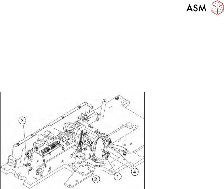
8.1 Overview of main assemblies
Fig.224: Main flip unit assemblies
1. Flip head
2. Return unit
3. Flip unit base plate
4. Nozzle support
8 Flip unit
8.2 Overview of spare parts
174 Service Manual SIPLACE Wafer System (SWS) 11/2018
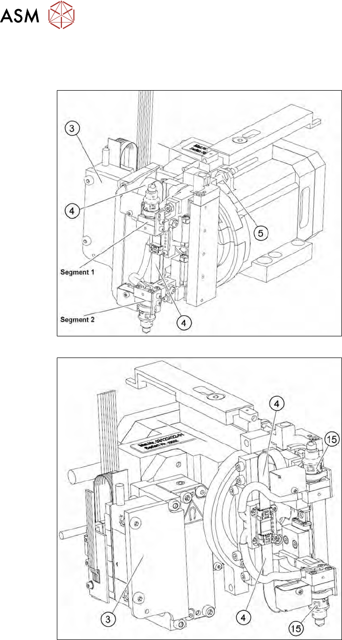
8.2 Overview of spare parts
Flip head
Fig.225: Flip head - view from behind
Fig.226: Flip head - view from the front
8 Flip unit
8.2 Overview of spare parts
Service Manual SIPLACE Wafer System (SWS) 11/2018 175
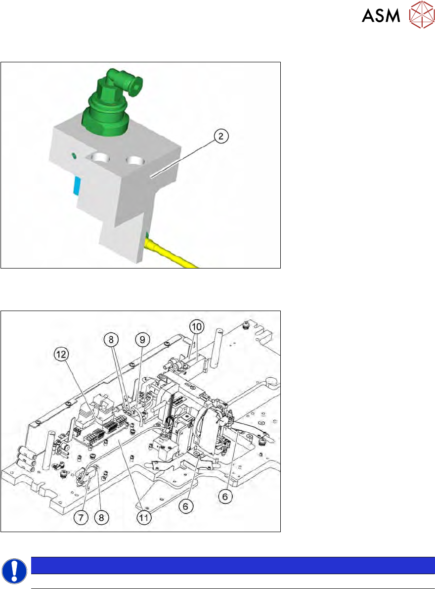
Return unit
Fig.227: Return unit
Flip unit - base plate
Fig.228: Base plate - flip unit
NOTICE
The reset button on the USB-IO-Rev.2 board (11) may not be used (firmware version).