00195982-03_SM_SWS_EN.pdf - 第293页
12 Wafer stretcher 12.5 Overview of wafer stretcher parts Service Manual SIPLACE Wafer System (SWS) 11/2018 293 12.5 Overview of wafer stretcher parts Fig.413: The following wafer stretcher parts were removed: 1. Wafer …
12 Wafer stretcher
12.4 Removing the wafer stretcher
292 Service Manual SIPLACE Wafer System (SWS) 11/2018
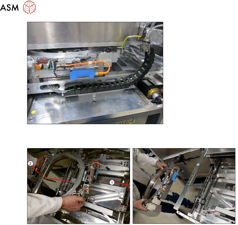
Fig.411:
► Take care when pushing the wafer stretcher in the Y direction. The cable of the rolled out
power chain could get caught on the upper assemblies.
Fig.412:
► Push the wafer changer to a back position (1) and unthread the wafer stretcher carefully,
under and out through the frame (2).
12 Wafer stretcher
12.5 Overview of wafer stretcher parts
Service Manual SIPLACE Wafer System (SWS) 11/2018 293
12.5 Overview of wafer stretcher parts
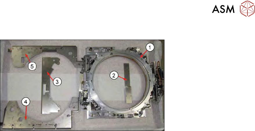
Fig.413:
The following wafer stretcher parts were removed:
1. Wafer stretcher frame (here: 12")
2. Cover plate board
3. Cover plate clamping and lifting cylinder
4. Downholder plate, left
5. Downholder plate, right
The above mentioned parts are needed for installation. All the screws and fastenings required are
provided with the delivery.
12.6 Fitting the wafer stretcher
The installation is shown using the example of a 12" wafer stretcher. The procedure for an 8" wafer
stretcher is identical.
If the wafer stretcher fitted is a retrofit, refer to chapter 12.4 "Removing the wafer stretcher" [}279].
Identical installation steps will be clearly indicated. This makes it easier to understand the installa-
tion process.
12.6.1 Preparations for fitting the wafer stretcher
The following conditions need to be fulfilled in order for the wafer stretcher to be fitted:
●
A wafer table has been removed.
●
Another wafer stretcher has been removed.
Make sure that the die ejector is in a low position.
For an overview of the wafer stretcher parts, refer to section 12.5 "Overview of wafer stretcher
parts" [}293].
12 Wafer stretcher
12.6 Fitting the wafer stretcher
294 Service Manual SIPLACE Wafer System (SWS) 11/2018
12.6.2 Fitting the wafer stretcher to the guide trolley
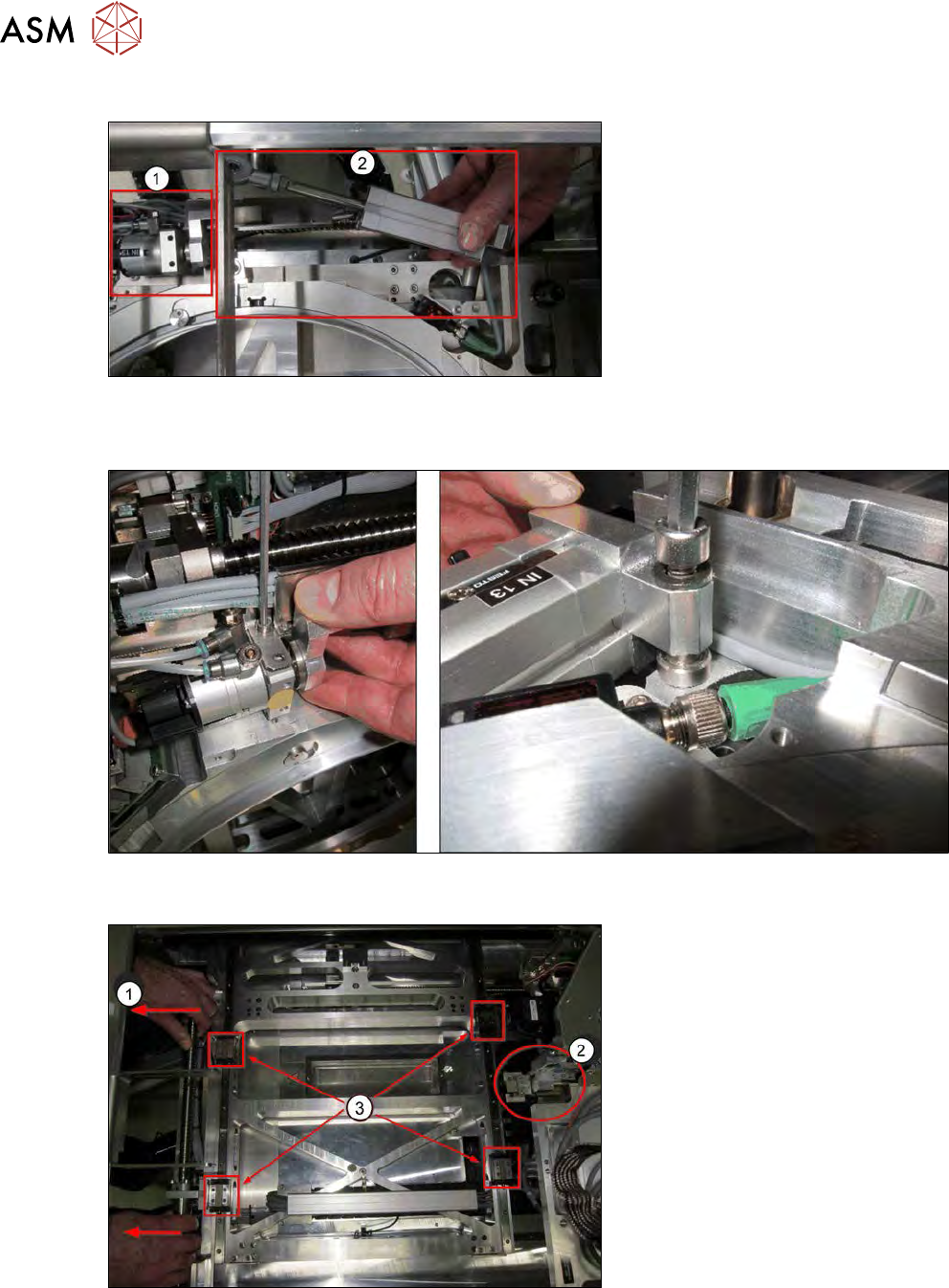
Fig.414:
► Dismantle and remove the clamping cylinder (1) and the lifting cylinder (2) from the wafer
stretcher. The diagram is only an example, as it shows the dismantled state in the SWS!
Fig.415:
► To dismantle, remove the two screws on the cylinders.
Fig.416:
► Pull the X/Y table fully over to the wafer lift side (1).
► Position the wafer changer (gripper) right at the back (2).
► Clean the surface of the guide trolleys (3).
► First position the guide trolleys roughly over the fastening holes in the wafer stretcher.