00195982-03_SM_SWS_EN.pdf - 第370页
15 Calibration 15.3 Calibration die handling - flip unit 370 Service Manual SIPLACE Wafer System (SWS) 11/2018 Holding cylinder of the Z axis – current version with grub screw Fig.532: Current SWS are equipped with a gr…
15 Calibration
15.3 Calibration die handling - flip unit
Service Manual SIPLACE Wafer System (SWS) 11/2018 369
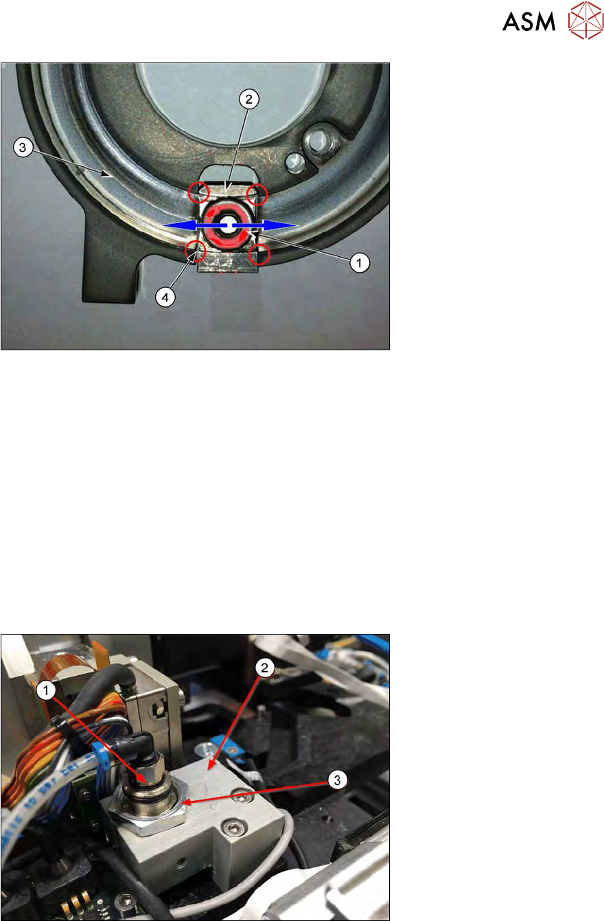
Fig.530:
► The ball bearing of the Z axis (1) has to move smoothly over the edges (4) between the race-
way (3) and the actuator of the Z axis (2).
► The holding cylinder of the Z axis keeps the actuator in the upper position to prevent a crash
of the Z axis when the SWS is powered off.
► If this position is too low or too high, the ball bearing hits the edges between the actuator (2)
and the raceway (3) and the rotary axis cannot move smoothly.
► The position of the holding cylinder Z axis must be adjusted.
The difference between the old and the current version for locking the holding cylinder is only the
locknut or grub screw.
The procedure to adjust the position of the holding cylinder is identical (see next chapter).
15.3.1.1 Different locking systems for the holding cylinder
Holding cylinder of the Z axis – old version with locknut
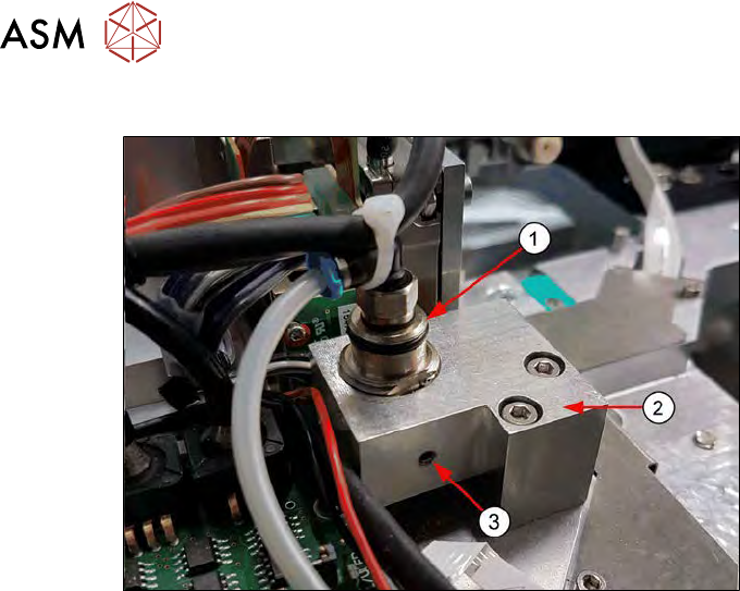
Fig.531:
Old SWS are equipped with a locknut to fix the position of the holding cylinder Z axis.
1. Holding cylinder (cartridge cylinder [00385277-xx])
2. Cylinder holder [00385089-xx]
3. Locknut (for locking the holding cylinder), open-end wrench size 19
15 Calibration
15.3 Calibration die handling - flip unit
370 Service Manual SIPLACE Wafer System (SWS) 11/2018
Holding cylinder of the Z axis – current version with grub screw
Fig.532:
Current SWS are equipped with a grub screw to fix the position of the holding cylinder Z axis!
1. Holding cylinder (cartridge cylinder [00385277-xx])
2. Cylinder holder [00385089-xx]
3. Grub screw (for locking the holding cylinder) M3x8 (Allen key 1.5mm)
15 Calibration
15.3 Calibration die handling - flip unit
Service Manual SIPLACE Wafer System (SWS) 11/2018 371
15.3.1.2 Adjustment of the holding cylinder Z axis
Tools required
●
Open-end wrench size 19 → for the old version with locknut
●
Allen key 1.5mm → current version with grub screw
Preconditions
Before you can adjust the height of the holding cylinder, loosen:
●
the locknut at the holding cylinder (old version) → with open-end wrench, size 19
●
the grub screw at the holding cylinder (current version) → Allen key 1.5
Procedure
NOTICE
Remove the grub screw almost completely so that you can rotate the holding cylinder up
and down easily. The grub screw must no longer touch the surface of the holding cylinder!
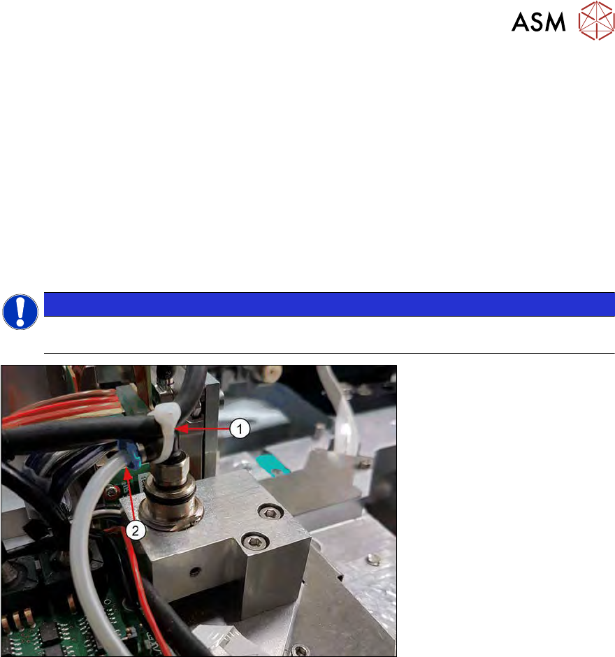
Fig.533:
► Remove the cable tie (1) and the air tube (2) from the holding cylinder. In doing so, you en-
sure that the holding cylinder for the adjustment in Z direction can be moved freely and that no
compressed air for the retraction function is applied to the cylinder.
► If the SWS is in emergency mode, no air supply is applied to the holding cylinder!
► To check the position of the holding cylinders, open emergency loop, so that all axes are
powerless. Then move the rotary axis by hand (see 15.3.1.1 "Different locking systems for the
holding cylinder" [}369]).
For adjusting of the holding cylinder of the Z axis, proceed as follows: