RS-1_instruction manual.pdf - 第1002页
Part 2 D etaile d Descript ion of E ach Functi on Chapter 12 Handling th e Optional Device s 12 - 118 5) <Selected p osition> button When you press t he <Se lected pos ition> butt on on the right side of the …
Part 2 Detailed Description of Each Function Chapter 12 Handling the Optional Devices
12-117
(2) How to set
Attach a nozzle on the selected head, and measure the height of the nozzle tip (to be reflected in
the “Nozzle height”) and the external width of the nozzle (to be reflected in the “Nozzle No”) with
laser. In addition, the vacuum value is automatically obtained.
To attach a nozzle on a head, manually attach it.
1) Nozzle No
Specify the nozzle number for a head number shown on the left side of the screen.
a) Enter the number of a nozzle to be assigned to the head number.
b) The row of a nozzle number in which a focus is located can be specified. Validate the
entered character with the <ENTER> key or the “field move” key. Enter a nozzle number
within the setting range shown below. Note that you cannot enter the number of an
unused head.
No.
Input item
Setting range
1 Nozzle No
Enter one of the registered nozzle numbers in the range of 7100 to
8999. Or do not enter any number (that is, no nozzle assignment).
After deleting a value entered in a cell with the <DEL> key or the <BACK SPACE> key,
press the <ENTER> key or the “field movement” key to validate it. The nozzle assignment
to the corresponding head is cancelled, all data associated to the nozzle disappear.
2) Nozzle Type
Specify the type of a nozzle to be attached on the head whose number is specified.
No.
Setting item
Description
1 Manual Nozzle to be attached on a head manually
3) Vacuum
Specify a vacuum value to be applied when a nozzle is attached on the selected head.
Vacuum specified with this value is to be used to decide whether a nozzle exists or whether
there is any component.
Note that since laser is used to decide whether a nozzle is attached on a head or not or
whether a component exists or not, this setting value is used as auxiliary information.
4) Nozzle height
Specify the length offset value viewed from the reference nozzle.
This value is used to make fine adjustments of the height control when a component is
measured with laser.
Part 2 Detailed Description of Each Function Chapter 12 Handling the Optional Devices
12-118
5) <Selected position> button
When you press the <Selected position> button on the right side of the screen, attach a
nozzle on the head number on which the focus is located, and then set each value.
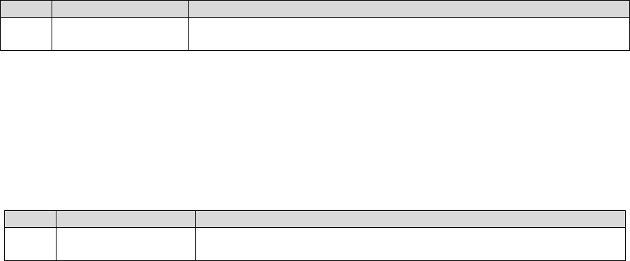
Note 1) If the obtained external size of the nozzle is not within the regulated range and the
system decides that there is no corresponding nozzle based on the nozzle width, the
system displays the following message. In this case, select a nozzle, and manually
enter each value.
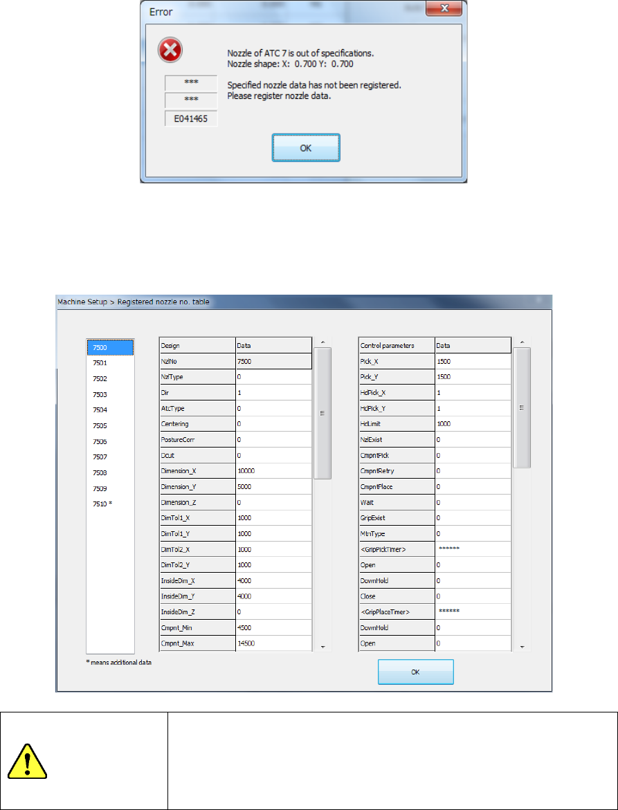
Note 2) If the obtained external size of the nozzle is not within the regulated range and the
system decides that there is a corresponding nozzle based on the nozzle width,
select a nozzle number from the nozzle list displayed on the following screen.
If the desired nozzle is not shown in the list, select the nozzle, and then manually
enter each value.
WARNING
When you select the <OK> button, the axes start moving.
Before pressing the <OK> button, be sure to confirm that there is
no one who is performing work in the machine.
To prevent injuries, do not put a hand inside the machine or close
your face or head to the machine while the machine is operating.
Part 2 Detailed Description of Each Function Chapter 12 Handling the Optional Devices
12-119
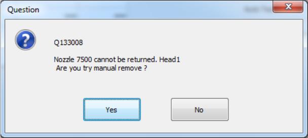
Note 3) If the acquired nozzle is not a manual nozzle, the following message will be
displayed. In this case turn off the machine and try installing the nozzle again.
Also, if the acquired nozzles are different or an error occurs, turn off the machine and
try installing the nozzle again.
6) Other item
When you press the <Head Wait Position> button of the menu item “Move Axis,” the head
moves to the head waiting position.