RS-1_instruction manual.pdf - 第62页
Part 1 B asic O peration Chapter 1 Overv iew of the Machine 1- 44 50 to 950 mm Stand ard specifi cation : 50 to 370 mm Extra - lar ge spe cificat ion: 5 0 to 560 mm Component not placeable area Pri nted circuit board spe…
Part 1 Basic Operation Chapter 1 Overview of the Machine
1-43
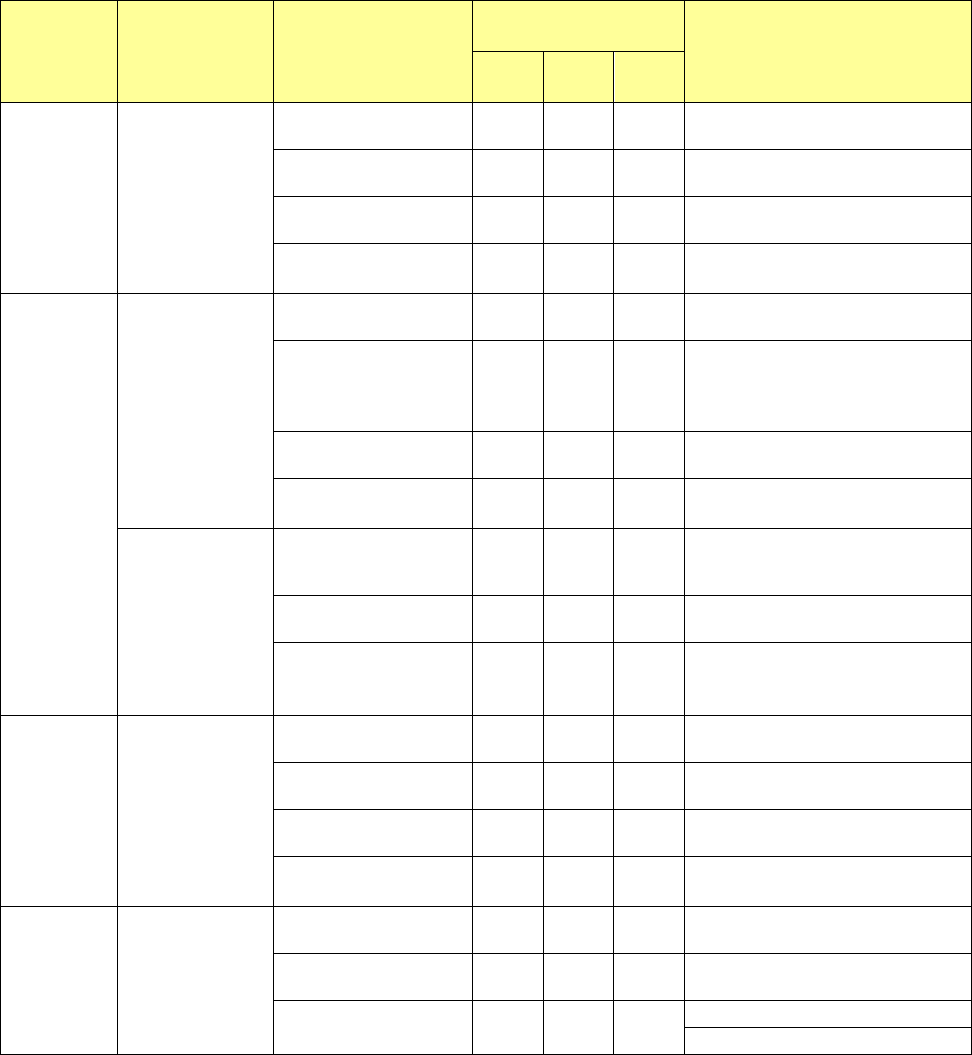
Component
name
Lead pitch/(size) Component size
Recognition with a VCS
(See Note 3)
Remarks
54mm
VCS
27mm
VCS
10mm
VCS
PLCC
Pitch:
1.27mm
More than □33.5mm, and
□50 mm or less
○
― △
More than □24 mm, and
□
33.5 mm or less
○ *5
― △
*5: □33.5 mm or less.
More than □20 mm, and
□24 mm or less
○
●◎ ●△
□20 mm or less ○
●◎ ●△
Q F P,
B Q F P,
QFN
Pitch:
0.4/0.5/0.65/0.8/
1.0mm
More than □33.5 mm,
and
□
50 mm or less
○ ― ―
More than □24 mm, and
□33.5mm or less
○*5 △*4 △*4
*4: Neither an HSPO image nor a QFN
image can be divided to be
recognized.
*5: □33.5 mm or less.
More than □20 mm, and
□
24 mm or less
○ ●◎ ●
□20 mm or less
○ ●◎ ●
Pitch:
0.2mm
More than □24 mm, and
□33.5 mm or less
― △*4 △*4
*4: Neither an HSPO image nor a QFN
image can be divided to be
recognized.
More than □20 mm, and
□
24 mm or less
― ○ ○
□20 mm or less
― ○ ○
BGA
Pitch 1.0 mm or
more, and less than
2.0 mm (when
zigzagging
alignment: 3.0
mm or less) (Ball
diameter: 0.4 mm
or more, and 1.0
mm or less)
More than □33.5 mm,
and
□
50 mm or less
○ ― ―
More than □24 mm, and
□33.5 mm or less
○*5 △ △
*5: □33.5 mm or less.
More than □20 mm, and
□
24 mm or less
○ ●◎ ●
□20 mm or less
○ ●◎ ●
FGBA
Pitch: 0.25 mm or
more
(Ball diameter:
0.1 mm or more)
More than □24 mm, and
□33.5 mm or less
― △ △
More than □20 mm, and
□
24 mm or less
― ○◎ ○
□20 mm or less
― ○◎ ○
Note 1: Even a component whose lead pitch is regulated respectively such as a QFP can be recognized with a pitch
not described above. (This machine shall be able to recognize a pitch not described in the table above with
considering variation in lead pitches.) In such a case, a pitch within a range of the minimum one to the
maximum one can be recognized. Note that a pitch from 0.38 mm can be recognized if the minimum pitch is
0.4 mm.
Note 2: See the item (1) “Applicable component sizes” of Section 1.5 “Applicable components and packaging styles”
for the size of a component to be applied when its image is divided to be recognized. A BGA or FBGA can
be recognized even though its vertical pitch is different from its horizontal pitch.
Note 3: The component size of the VCS collective recognition is
□
50mm at the maximum; that of the VCS
multi-recognition is
□
14mm at the maximum.
Note 4
:
As for a square chip, the system decides the side of a square chip resistor whose size is from 03015 to 6432
only. However, the system may not be able to correctly decide the side of a component whose front side
brightness is not quite different from that of the rear side or the side of a component whose brightness varies
depending on lots.
Part 1 Basic Operation Chapter 1 Overview of the Machine
1-44
50 to 950 mm
Standard specification: 50 to 370 mm
Extra
-
large specification:
50 to 560 mm
Component not placeable area
Printed circuit board specifications
(1) Board requirements
Minimum
size
(L x W)
Maximum size (L x W)
Thickness
T
Maximum
allowable
mass
Allowable warpage
1-buffer 3-buffer
Standard
board size
50 x 50 mm
650 x 370 mm
(One clamp)
950 x 370 mm
(Twice clamp)
360 x
370 mm
0.3~4.0 mm 3,000 g
0.2 mm or less per 50 mm in
the up/down direction, and 1
mm or less
upwards/downwards
(Conforming to the JIS B
8461.)
Extra-large
board size
650 x 560 mm
Note: “L” stands for the dimension in the board transporting direction, while “W” stands for the
dimension in the direction at right angles to “L,” and “W/L” shall be equal to 2 or less.
Note: A low reflectance PWB may not be detected by a conveyor sensor, independent of materials and
colors of the PWB.
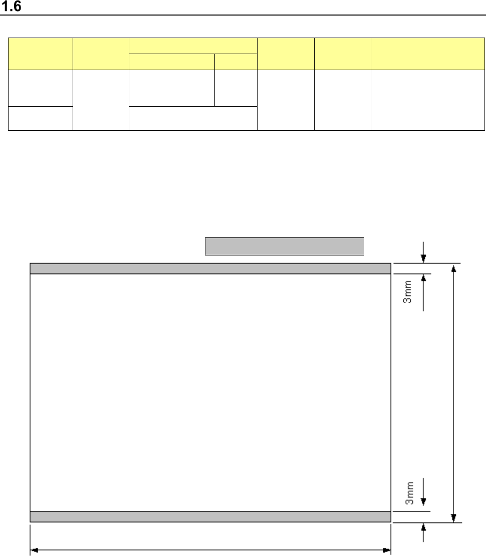
(2) Board limitations
1) Topside of a board
Conveyor rail fixed side
Part 1 Basic Operation Chapter 1 Overview of the Machine
1-45
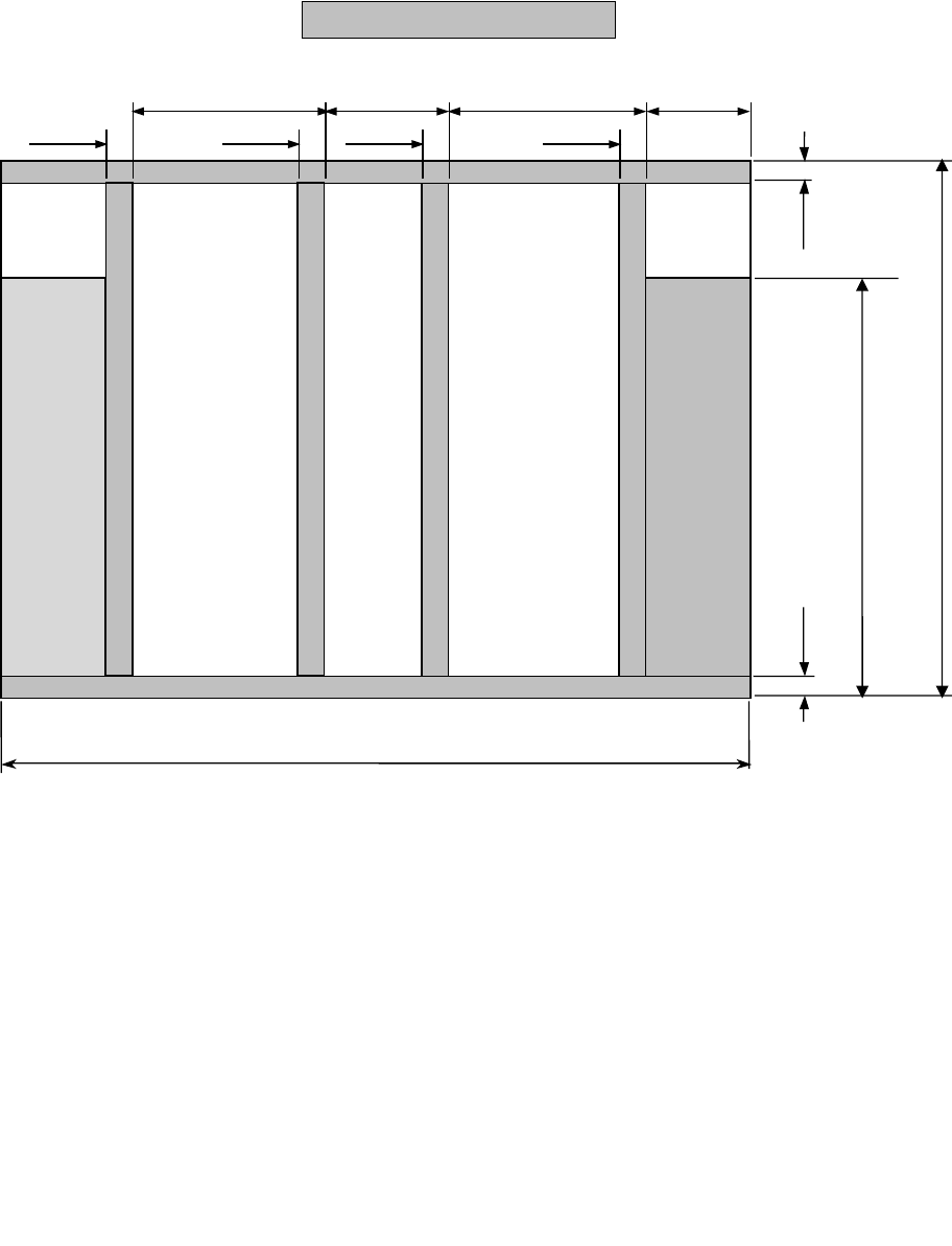
2) Bottom side of a board
Any support pin cannot set in this area range.
Standard specification:
50 to 370mm
Extra
-
large specification:
50 to 560mm
3mm
3mm
57.5mm
8mm
8mm
220mm
87mm
8mm
8mm
220mm
Left → Right
flow
Stopper movable range 0 to 320mm
Left ← Right
flow
Conveyor rail fixed side 50 to 650 mm