RS-1_instruction manual.pdf - 第585页
Part 1 B asic O peration Chapter 4 Cr eating a Produc tion Progra m 4- 250 5) Result of inspect The image r ecognition r esult or t he coplanarit y check result is dis played her e. ● S tatus If the mac hine measur es an…
Part 1 Basic Operation Chapter 4 Creating a Production Program
4-249
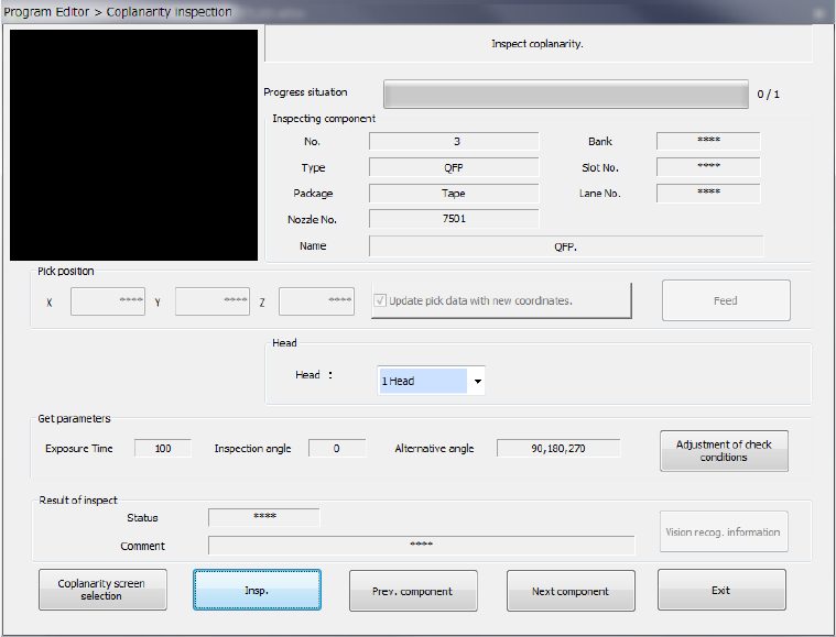
(3) Operation of a coplanarity check
Create data of a production program from “Component data” to “Vision data,” and then select the
[Meas/Insp] command from the menu, and the [Coplanarity inspection] command on the displayed
menu.
The screen like one shown below appears.
1) Component being inspected
Component data necessary for a coplanarity check is displayed here.
2) Pick position (Pick-up position of a component to be measured)
Data on a position from which a component is picked up is displayed here. You can
change this pick-up position to the pick-up position of the previous alternate component or
that of the next alternate component also. If there is not any Pick data or if an MTC is
specified, each item is dimmed on the screen, so you cannot change the component pick-up
position, knock the feeder, or perform teaching operation.
● Update pick data with new coordinates
Specify whether to update Pick data with the taught result.
When you do not place a checkmark in this check box, the coordinates are applied to the
pick-up operation this time only.
● Feed
This button knocks a feeder to feed components.
3) Head (to be used)
You can select a head to be used for inspection. Select the desired head from the list of the
combo box.
4) Get parameters
When you press the <Adjustment of check conditions> button, the system obtains the
following data that allows the coplanarity inspection: “Exposure time,” “Inspection angle”
and “Alternative angle,” which means the alternative inspection angle.
Part 1 Basic Operation Chapter 4 Creating a Production Program
4-250
5) Result of inspect
The image recognition result or the coplanarity check result is displayed here.
● Status
If the machine measures an object successfully, “OK” is displayed here. Otherwise,
“NG” is displayed.
● Comment
The cause of an error is displayed here.
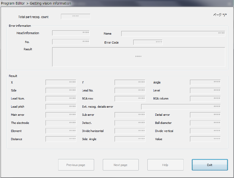
● <Vision recog. information> button
If the image check result is “NG,” this button allows you to display the detailed
information on the error on the screen.
The machine can display the detailed data on the 16th error from the latest one.
The detailed information on image recognition errors is displayed on the screen from the
latest one.
<Previous page> : Displays information on the previous image recognition error.
<Next page> : Displays the next information on the current image recognition error.
<Help> : Displays the Help function appropriate for the image recognition error
displayed currently.
<Exit> : Closes the image recognition error information screen.
Part 1 Basic Operation Chapter 4 Creating a Production Program
4-251
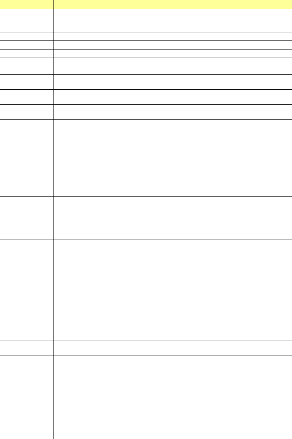
Each item of the detailed image recognition error information is described in the table below.
Displayed item
Description
Total part recog.
count
Number of times the machine recognized a component
Page
Page number of the displayed image recognition information
Head information
Head number
Name
Component name specified in Component data
No.
Number specified in Component data
Error Code
Actual image recognition error code
Result
Unprocessed character string of the result
X
Recognition result (Offset for the center of the screen in the X direction)
The right direction of the VCS monitor is positive.
Y
Recognition result (Offset for the center of the screen in the Y direction)
The upper direction of the VCS monitor is positive.
Angle
Recognition result (Offset for the center of the screen in the θ direction)
The anticlockwise direction of the VCS monitor is positive.
Side
Side at which an error was detected (Up/down/left/right)
This is not the side displayed on the monitor but the side of the Top-View specified in Vision
data.
Lead No.
Number of a lead at which an error was detected (from 1).
Lead number specified anticlockwise in the Top-View specified for a missing lead
If two or more error occurs, the number of a lead at which the machine detected an error for
the first time is displayed here. For a general-purpose vision component, the lead (ball)
number counted from the first element is displayed here.
Level
If a lead bending error occurs, the lead bending ratio to the lead pitch (%) is displayed here.
If a ball is deformed or if a ball diameter error occurs, the deformation ratio to the ball
diameter (%) is displayed here. (in increments of 0.1 %)
Lead Num.
Total number of leads detected actually
BGA row
Row number of a ball of an area array component at which an error was detected
This is a line number displayed on the VCS monitor not related to the Vision data. (That is,
a line number sequentially assigned from 0 and counted from the top of the VCS monitor to
the bottom.) If two or more error occurs, the row number of a ball at which an error is
detected first is displayed here.
BGA column
Column number of a ball of an area array component at which an error was detected
This is a column number displayed on the VCS monitor not related to the Vision data.
(That is, a column number sequentially assigned from 0 and counted from the left of the
VCS monitor to the right.) If two or more error occurs, the column number of a ball at
which an error is detected first is displayed here.
Lead pitch
Actual lead (ball) pitch of a component that caused a lead (ball) pitch error
This is output only for a component whose actual lead (ball) pitch is detected with the
machine. (in increments of 0.1 μm)
Ext. recog. details
error
5-digit character string indicating error information of an outline recognized component
“XX” of “XXYYY” indicates where the error occurred, and “YYY” indicates the cause of the
error.
Main error
Main error code of a general-purpose vision component (including some BGA components)
Sub error
Sub error code of a general-purpose vision component (including some BGA components)
This sub code indicates a specific internal event.
Detail error
Detailed error code of a general-purpose vision component (including some BGA
components)
The electrode
Number of leads of an extended-lead connector component specified in Vision data
Detect.
Total number of leads of an extended-lead connector component that were able to be
detected actually
Ball diameter
Actual diameter of a ball whose diameter and deformation were detected (in increments
of 0.1 μm)
Element
Number of an element group of a general-purpose vision component at which an error
occurred
Divide horizontal
If the division recognition pitch (in the horizontal direction) specified in a production
program is different from the actual movement distance, this difference is output here.
Divide vertical
If the division recognition pitch (in the vertical direction) specified in a production program
is different from the actual movement distance, this difference is output here.