RS-1_instruction manual.pdf - 第871页
Pa r t 2 Det ai l ed Des c r i pti on o f Ea c h Fu nc ti on Chapte r 1 1 S el f - diagnosis Func ti on 11 - 13 Laser/sensor height W hen you selec t the [Laser /se nsor hei ght] com m and f r o m the “ Self C heck ” men…
Part 2 Detailed Description of Each Function Chapter 11 Self-diagnosis Function
11-12
11.3.3.4.2 Saving the settings and quitting the screen
There are two push buttons, <OK> and <CANCEL> on each of the setting screens: “Head
Offset,” “Laser/sensor height” and “VCS camera offset.” Even though you press the <OK> button
on each screen, any value is not stored yet at this point.
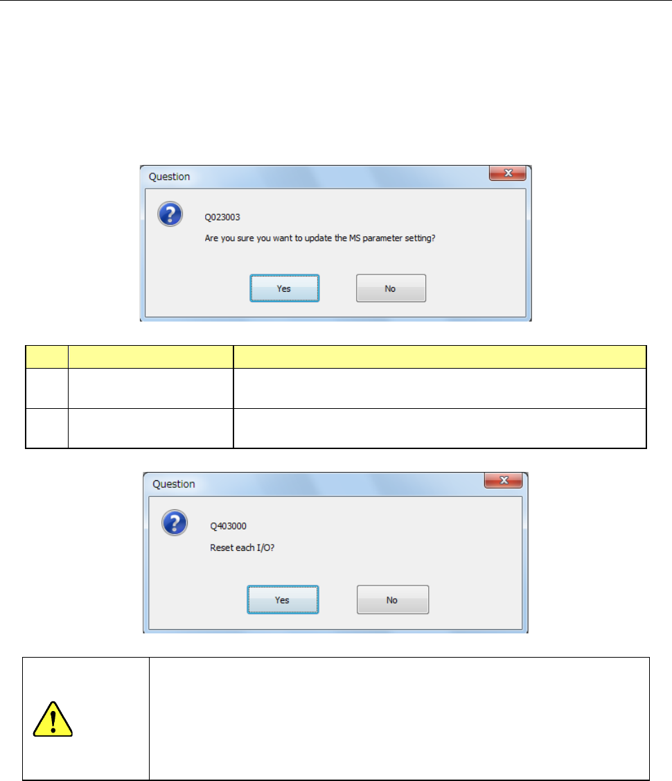
When you click the close <×> button displayed at the upper right corner of the screen or press the
“Exit” button in the Information area after measuring values to be set with each item, the “Question”
dialog box that asks you whether to save the values appears on the screen.
When you select the <Yes> button, the values are saved.
No. Selection of the button Process
1 Yes
Saves the setting values and displays the “Question” message
for setting the safety direction of each I/O.
2 No
Disables the setting values and displays the “Question” message
for setting the safety direction of each I/O.
WARNING
When you select the <Yes> button, the axes start moving and then the
machine starts setting the safety direction of each I/O.
Before pressing the <Exec> button, be sure to check to see if there is no
one who is operating inside the machine. To prevent injuries, do not put a
hand inside the machine or close your face or head to the machine while
the machine is operating.
Part 2 Detailed Description of Each Function Chapter 11 Self-diagnosis Function
11-13
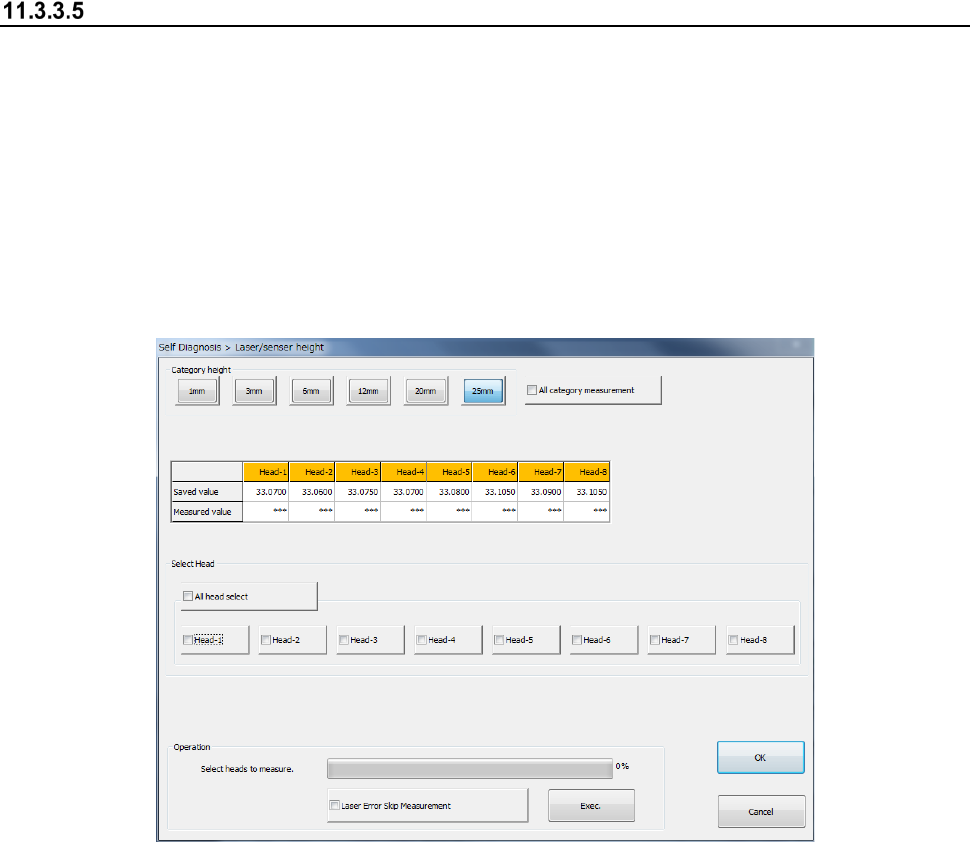
Laser/sensor height
When you select the [Laser/sensor height] command from the “Self Check” menu, the
“Laser/sensor height” dialog box appears on the screen.
The machine sets the laser/sensor measurement height from the origin of the Z-axis of each head
viewed from the topside of a board.
If a laser recognition error frequently occurs, check the settings of the “Component data” of a
production program, and then set the menu item “ATC nozzle setup” invoked from the “Machine
Setup” screen. If the error persists even after you set this menu item, set the measurement
height with this function again.
After setting the laser/sensor height again, be sure to set the menu item “ATC nozzle setup” again.
(1) Category height
Select the category height to be measured. When you select the “All category measurement”
check box, the machine measures the heights of all categories and those of all heads
continuously.
(2) Saved value/Measured value
The machine displays the values set with the MS Parameter in the “Saved value” columns,
and the measured values in the “Measured value” columns.
Immediately after this dialog box appears or for a head not measured yet, any value is not
displayed in the “Measured value” column.
After measurement, the measured value is displayed in blue in the column for the
corresponding head.
If any measurement error occurs, “Err” is displayed in red.
(3) Select Head
Select a head to be measured with checking off the corresponding check box in the “Select
Head” group. You can select two or more heads to be measured at the same time.
When you select the <All head select> button, you can select or deselect all heads of a head
unit(s) of each device.

Part 2 Detailed Description of Each Function Chapter 11 Self-diagnosis Function
11-14
(4) Operation
1) Progress bar
The progress of measurement is indicated with this bar. When measurement finishes, the
progress bar indicates “100 %.”
2) Laser Error Skip Measurement
When you check off the check box “Laser Error Skip Measurement” and press the <Exec.>
button, the machine skips a laser error.
Even though a laser recognition error occurs or the measurement result is not within the
regulated range, the machine just displays “Err” without displaying the “Question” message,
and then measures a head if there is any head not measured yet within the target head unit.
To measure again a head causing an error, select the head, and then press the <Exec.>
button after the machine finishes the current measurement (that is, after the progress bar
indicates 100 %).
3) <Exec.> button
When you press the <Exec.> button, each head unit moves to the waiting position to start
measurement.
See the following subsection “How to set” for details.
WARNING
When you press the <Exec> button, the axes start moving.
Before pressing the <Exec> button, be sure to check to see if there is
no one who is operating inside the machine. To prevent injuries, do
not put a hand inside the machine or close your face or head to the
machine while the machine is operating.