RS-1_instruction manual.pdf - 第200页
Part 1 B asic O peration Chapter 2 Pr oduction 2- 89 10) Error (D etail – Copla narity) No. Displayed er ror me ssage 1 A coplanarity jud gemennt error. 2 A coplanarity ce ntering positio n error. 3 A lead count err or. …

Part 1 Basic Operation Chapter 2 Production
2-88
No.
Displayed error message
91 MTC COMM ERR (Power Off)
92 Step Number of Tray is Wrong
93 MTC is not Available in Setup Data
94 Not Finding STX ETX
95 Undefined Command Code is Specified
96 Parts Request Send Multiplexy (WAIT)
97 Parts Request Send Multiplexy (KICK)
98 Parts Request is Abnormal
99 Response Time Out
100 MTC Initialize Incompletely
101 Unmovable by Off-line
102 Unmovable by Air-Down
103 IPC Object Close Error (MTC-1)
104 IPC Object Close Error (MTC-2)
105 IPC Object Close Error (MTS-1)
106 IPC Object Close Error (MTS-2)
107 IPC Object Close Error (DTS-1)
108 IPC Object Close Error (DTS-2)
109 IPC Object Close Error (MTC-1)
110 Move error
111 Retry over
112 No component
113 Offline
114 Supply
115 Pick miss
116 Time Out (Ready Waiting Observation 10sec)
117 Time Out (Sync Character Observation 4sec)
118 Time Out (ETX Observation 3sec)
119 MTC Power Off
120 Time Out (Responseless Observation 60sec)
121 Receive Data Validity Error
122 Ring Buffer Access Error
123 Time Out (Data Link Release 1)
124 Time Out (Data Link Release 2)
125 MTC Communication Initialize Failed

Part 1 Basic Operation Chapter 2 Production
2-89
10) Error (Detail – Coplanarity)
No.
Displayed error message
1 A coplanarity judgemennt error.
2 A coplanarity centering position error.
3 A lead count error.
4 A colinearity judgemennt error.
5 A coplanarity unit error.
6 A illegal data or illegal operation.
7 A coplanarity adjust error.
8 A time-out or other error.
9 A hardware error of coplanarity controler.
10 A measurement software error.
11 A lasor diode is abnormal.
12 A cable connection error.
13 The motor revolution is abnormal.
14 A memory of sencer is abnormal.
15 A initialize error of coplanarity unit.
16 An axis error of coplanarity measurement.
17 The component type can not be measured.
18 The component size is too large.
19 The component size is out of range.
20 The component height is too high.
21 The meas. mode isn't corr. or the compo. cann't be measured.
22 The electrode can not be measured.
23 A coplanarity sensor is unused.
Part 1 Basic Operation Chapter 2 Production
2-90
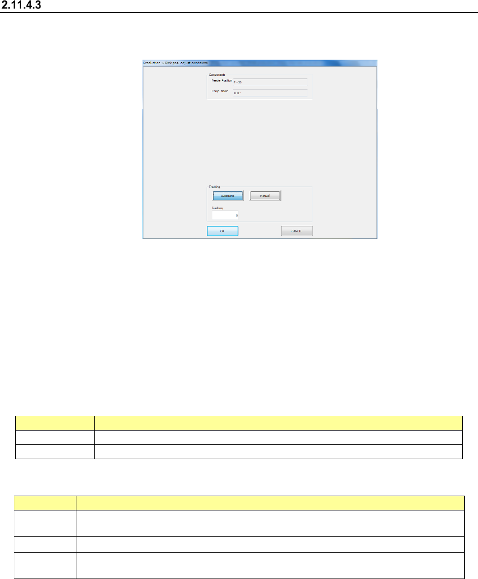
Pick position correction
(1) Overview
When you press the “Trace” button displayed in the Operation area while the “Retry list” is
displayed on the screen, the “Pick pos. adjust conditions” screen appears.
You can track a component pick-up position under the conditions specified on this screen to
correct the component pick-up position.
Components whose pick-up position is corrected are automatically replenished.
What to correct varies depending on the displayed data on the “Retry list” you invoked:
♦ When the “Retry list (Supplier)” appears
The system corrects a component pick-up position of the displayed component supply unit.
♦ When the “Retry list (Not placed)” appears
The system corrects pick-up positions of component supply units assigned to all unplaced
components.
(2) Displaying the conditions for correcting the component pick-up position
1) Components
The pick-up position and name of a component to be corrected appear here.
Menu item
Description
Feeder Position
Displays the component pick-up position to be corrected.
Comp. Name
Displays the name of a component whose pick-up position is to be corrected.
2) Tracking
How to track a component pick-up position to be corrected appears here.
Menu item
Description
Automatic
The system stops at a component pick-up position for the certain time after correcting it, and
automatically moves to the next pick-up position.
Tracking
Specify the time period while the system has to stop when you select “Automatic” above.
Manual
The system pauses for the certain time after correcting the component pick-up position. The
system corrects the next pick-up point according to the operator’s input.
3) <OK> button and <CANCEL> button
When you press the <OK> button, the system tracks a component pick-up position, and
corrects it. Details of this operation are described in the next section.
When you press the <CANCEL> button, the system finishes correcting a component
pick-up position.