RS-1_instruction manual.pdf - 第558页
Part 1 B asic O peration Chapter 4 Cr eating a Produc tion Progra m 4- 223 6) Zoom When you ch eck the < Zoom> check b utton, you can enlarge the image shot w ith the c amera and superim posed on the sc reen if you…
Part 1 Basic Operation Chapter 4 Creating a Production Program
4-222
2) Pick position
Information on the current pick-up position is displayed here.
a) Package
Displays the packaging style of a component being tracked.
b) Slot/Lane
Displays the fixing hole position of a component being tracked or the lane number of the
component if it is supplied by a stick feeder.
c) Bank
Displays the bank at which the component pick-up position is located.
d) Supply
Displays the component supply angle.
e) Tray corner number
Displays the tray corner number when a component is supplied with a tray feeder.
f) Comp. name
Displays the name of a component being tracked.
g) Feed pitch
Set a value when you want to change the feed pitch of the electric feeder. You can select
the feed pitch that can be set for the electric feeder being tracked.
3) Pick position Set
a) Current position
The “Current position” shows the XYZ coordinates of the pick-up position of a component
being tracked.
As the component position, four corners of the component or the center of the pick position
is displayed.
CENTER: Shows the center of the component.
TOP-L: Shows the upper left corner of the component.
TOP-R: Shows the upper right corner of the component.
BTM-L: Shows the lower left corner of the component.
BTM-R: Shows the lower right corner of the component.
b) Setting position
The “Setting position” indicates the coordinates of the component pick-up position set with
the production program.
The coordinate value can be changed by manual input or teaching.
4) Inspection
These buttons allow you to inspect a component or change its data.
a) Component direction
Component direction inspection of a general-purpose vision component is performed.
See (10) "Component direction inspection under tracking" of Section 4.5.6.5 "Pick
position/Pick height" for details.
b) Data chg.
This button allows you to change a part of Component data.
See Section 2.11.2 “Edit Data” of Chapter 2 for details.
5) Progress
The progress bar advances one by one according to the position to be tracked. When you
move this progress bar while the system is stopping, you can move the camera to the
previous point or the next point. When you press the <Prev> button, the camera moves
back to the previous component pick-up position. When you press the <Next> button or
the <START> switch, the camera moves to the next component pick-up position.
Part 1 Basic Operation Chapter 4 Creating a Production Program
4-223
6) Zoom
When you check the <Zoom> check button, you can enlarge the image shot with the camera
and superimposed on the screen if you enable the option “Enable digital zoom teaching” on
the “Operation option” screen.
When the length of the longer side of the component outer dimensions is 2.26 mm or more,
the system does not enlarge any image shot with a camera regardless of the setting of the
“Operation option” screen.
When “the placement angle” + “the circuit angle” is not any of 0, 90, 180 and 270 degrees,
the system does not enlarge any image either.
The system switches the enlargement factors as shown below depending on the outer
dimensions of a component:
• 4x zoom (The option “Enable 4x zoom” has to be checked on the “Operation option”
screen.)
When the length of the longer side of a component is from 1.11 mm to 2.25 mm: the
displayed image is doubled in size.
When the dimension of the longer side is from 0.01 mm to 1.10 mm, the displayed image
is quadrupled in size.
• Without 4x zoom
When the length of the longer side of a component is from 0.01 mm to 2.25 mm, the
displayed image is doubled in size.
7) Feed
This button feeds a feeder displayed at the “Slot” field.
8) AUTO
This button makes a camera recognize the cavity and automatically teach it so that a
component can be located at the center position.
9) OK/CANCEL
These buttons are enabled only after you manually enter coordinates or change them by
teaching operation.
When you press the <OK> button, the system memorizes the XY coordinates in the
placement data.
If you do not want to memorize the changed values, press the <CANCEL> button.
When you press the <CANCEL> button, the coordinates changed by teaching operation are
reset to the previous values.
Part 1 Basic Operation Chapter 4 Creating a Production Program
4-224
(4) Operation during tracking of a component pick-up position
While the system is tracking a component pick-up position, you can use the following switches
and/or buttons to control the tracking operation.
Operation Operation panel Button on the screen
Start of tracking <START> switch <EXEC> button
Stop of tracking <STOP> switch
Moving to the previous point <Prev> button
Moving to the next point <STOP> switch <Next> button
End of tracking Press the <STOP> switch
when the system stops.
Press the <CANCEL> button
when the camera stops.
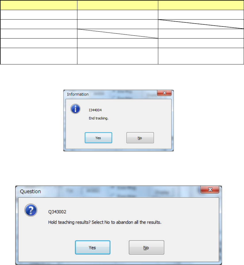
When the tracking is completed with operation steps described above, the following message
appears.
When you press <No> in the above dialog box, the screen returns to the “Pick position tracking”
screen. When you press <Yes>, the following message appears, prompting you to save the
teaching results.
When you press <No>, the coordinate values, which have been taught during the tracking
operation, are discarded and returned to the coordinate values before starting the tracking, and
then the tracking is completed.
When you select [Yes], the coordinate value is updated by the pickup coordinates changed during
tracking, and the tracking is finished.