RS-1_instruction manual.pdf - 第169页
Part 1 B asic O peration Chapter 2 Pr oduction 2- 58 No. Menu item Description 1 Feeder Pos ition Shows the c omponent supply position. For ETF8D or stick fe eder , the lane is di splayed in parent heses. 2 Cmp. Na me Sh…
Part 1 Basic Operation Chapter 2 Production
2-57
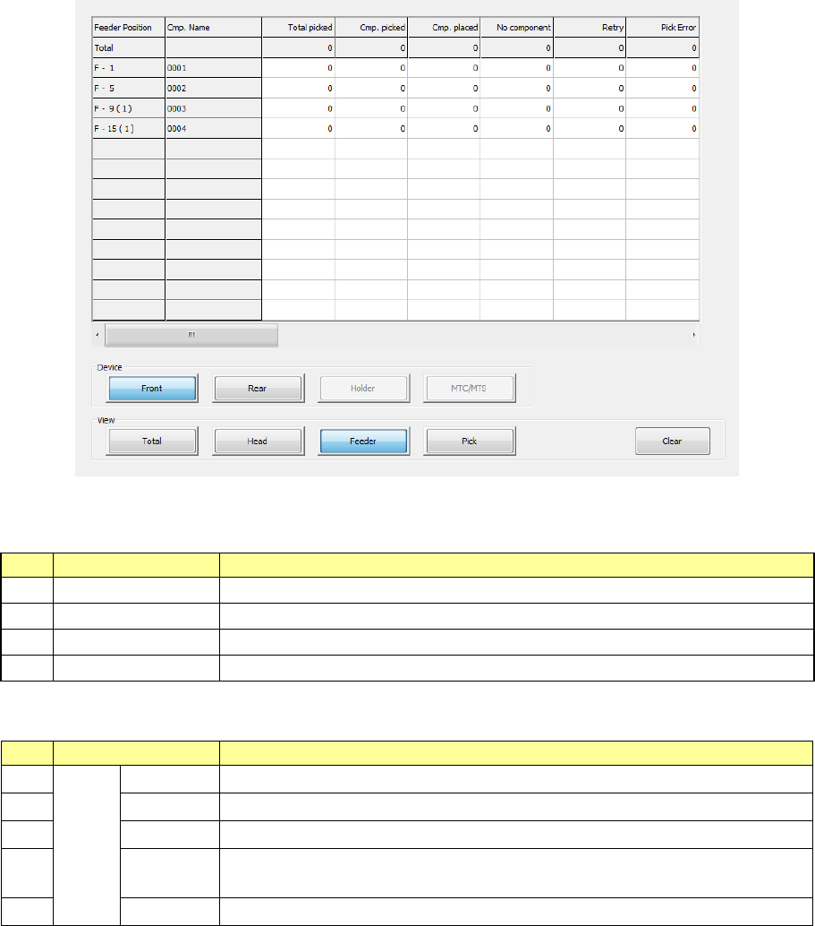
3) Management Info (Feeder)
The production management information per feeder is displayed.
When you select “Front” as the “View Bank,” the following screen appears.
“View Bank” allows you to select a bank on which a component is located to be displayed in the list
of the screen.
No.
Menu item
Description
1
Front
Shows only components set on the front bank.
2
Rear
Shows only components set on the rear bank.
3
Holder
Shows only components set on the holder or the DTS.
4
MTC/MTS
Shows only components set on the MTC or the MTS.
“View” allows you to change the displayed management information.
No.
Menu item
Description
1
View
Tot al Shows the total management information.
2
Head
Shows the production management information per head.
3
Feeder
Shows the production management information per feeder.
4
Pick Sorts the component pick-up rates at each component supplied position and
shows them.
5
Clear
Clears the production management information.
Part 1 Basic Operation Chapter 2 Production
2-58
No.
Menu item
Description
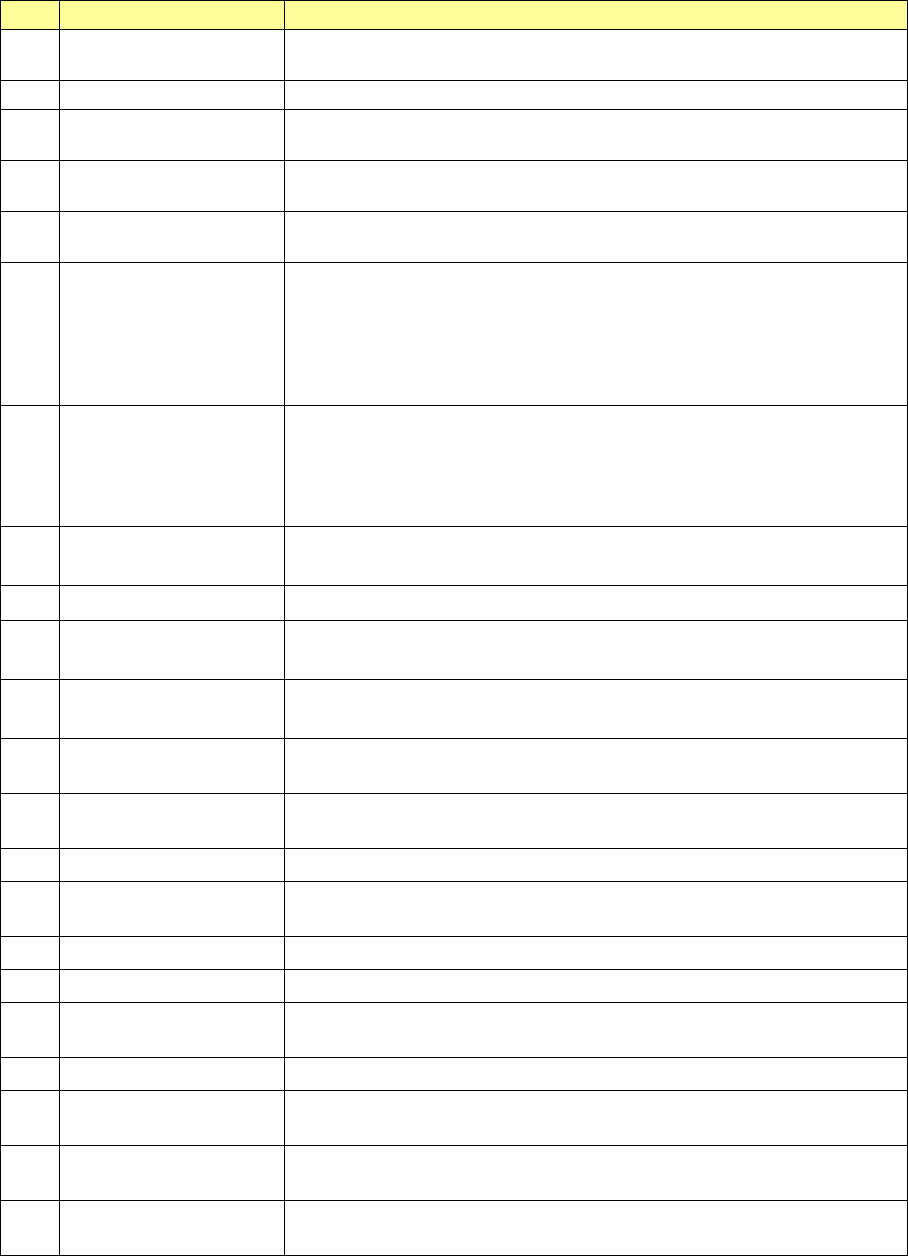
1 Feeder Position
Shows the component supply position.
For ETF8D or stick feeder, the lane is displayed in parentheses.
2
Cmp. Name
Shows the name of a component to be supplied.
3 Total picked
Shows how many times the component supply unit picked up a component.
(“Cmp. picked” + “Pick Error”)
4 Cmp. picked
Shows the number of components that were picked up with the component
supply unit successfully.
5 Cmp. placed
Shows the number of components that were picked from the component
supply unit and then placed on boards.
6 No component
Shows how many times components have run out on the component supply
unit.
When a feeder is used, this indicates the same thing as the menu item
“Retry” below. When you set the number of remaining components, this
shows how many times the “Number of retry over errors” + “Number of
remaining components” became “0.”
7 Retry
Shows how many times a retry over error occurred at the component supply
unit.
(The system picks up components the number of times set in the “Retry”
field on the “Component” data screen. If the system cannot pick up a
component, the value in this field increments by 1.)
8 Pick Error
Number of times the machine failed to pick up a component from the
corresponding feeder.
9 Cmp. Remove Shows how many times components were discarded.
10 Cmp. fall
Shows how many times a picked component dropped off before it was
placed on a board.
11 Cmp. takeout
Shows how many times a component was brought back without being
placed on a board.
12 LA Recog.
Number of times a laser recognition retry over error occurred at the
corresponding feeder.
13 Irregular dimensions
Shows how many times the system detected an irregularly shaped
component.
14 Verify Number of judgments as a verify error.
15 Tombstone
Shows how many times the system judged that a component picked up from
the component supply unit stood on its side.
16 Posture Shows how many times a component posture error occurred.
17 Laser angle error Shows how many times a laser angle error occurred.
18 Wrong Pick Pos
Number of times any other errors such as drop of a component were judged
to occur.
19 Vision Recog. Shows how many times an image recognition error occurred.
20 Copla error
Shows the number of components whose lead float error or ball height error
was detected with the coplanarity unit.
21 Lead
Shows how many times the system judged that a lead bend error occurred
during component recognition.
22 Other error
Shows how many times the system judged that an error other than those
above occurred.
- The total number of each item is displayed on the second line of the screen.
Part 1 Basic Operation Chapter 2 Production
2-59
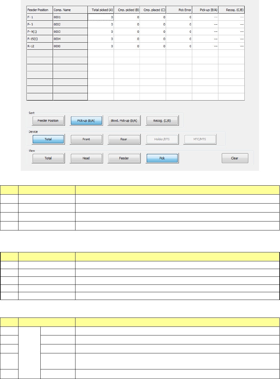
4) Management Info (Pick)
The system shows “the pick-up ratio per component supply position (Pick-up ratio = Number
of pick-ups / (Number of pick-ups + Number of pick-up errors))” on the screen.
The pick-up ratios are normally displayed on the screen in the order of ascending
pick-up ratios.
“Sort”: Select how to sort the pick-up ratios displayed in the list.
No.
Menu item
Description
1
Feeder Position↓
Sorts the pick-up ratios in the order of descending feeder positions to display them.
2
Pick-up (B/A)↓
Sorts the pick-up ratios in the order of ascending pick-up ratios to display them.
3
Bkwd. Pick-up (B/A)
Sorts the pick-up ratios in the order of descending pick-up ratios to display them.
4
Recog. (C/B)↓
Sorts the pick-up ratios in the order of ascending recognition ratios to display them.
“View Bank” allows you to select a bank on which a component is located to be displayed in the list
of the screen.
No.
Menu item
Description
1
Tot al
Shows all components.
2
Front
Shows only components set on the front bank.
3
Rear
Shows only components set on the rear bank.
4
Holder
Shows only components set on the holder or the DTS.
5
MTC/MTS
Shows only components set on the MTC or the MTS.
“View” allows you to change the displayed management information.
No.
Menu item
Description
1
View
Tot al
Shows the total management information.
2
Head
Shows the production management information per head.
3
Feeder
Shows the production management information per feeder.
4
Pick
Sorts the component pick-up rates at each component supplied position and
shows them.
5 Clear Clears the production management information.