RS-1_instruction manual.pdf - 第426页
Part 1 B asic O peration Chapter 4 Cr eating a Produc tion Progra m 4- 91 ② Ba l l informat ion a) W idth Enter the ba ll width (diam eter). b) N umber of balls (bott om, right, t op and left) Enter the num ber of balls …
Part 1 Basic Operation Chapter 4 Creating a Production Program
4-90
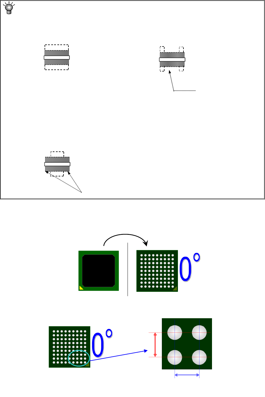
<Meaning and image of the lead recognition pattern
•
All: The system is supposed to
recognize all leads of a component.
•
Only the both ends lead: The system is
supposed to recognize only leads located at
both ends of a component.
• Both ends lead exclusion: The system is supposed to recognize only leads excluding ones
located at both ends of a component.
* Enter the number of leads to be recognized. (Not including the number of leads that
should be excluded.)
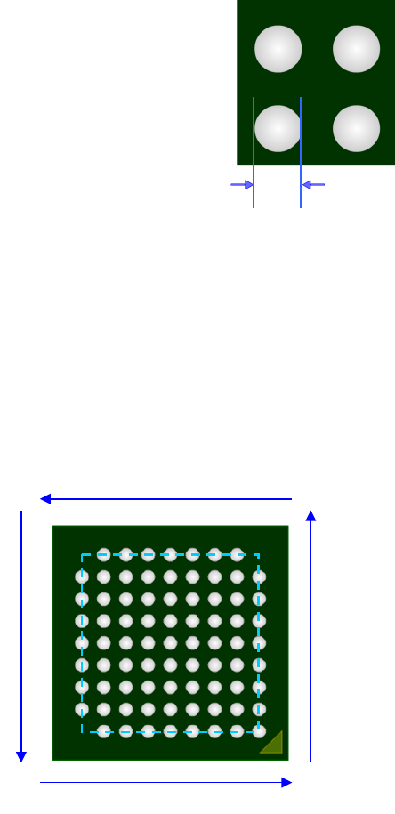
2) Component type: Ball component
* For vision data of the ball component, create data by component bottom view.
Set each ball information seen in the bottom view.
① Ball pitch
Enter the distance (X, Y) between balls.
The system will not
recognize the leads
located on the inside.
The system will not recognize the leads
located at both ends.
Recognized
Recognized
Recognized
Recognized
Recognized
Recognized
Recognized
Recognized
Top view
Bottom view
X
Y
Pitch between balls
Part 1 Basic Operation Chapter 4 Creating a Production Program
4-91
② Ball information
a) Width
Enter the ball width (diameter).
b) Number of balls (bottom, right, top and left)
Enter the number of balls on the outer periphery for each side.
Even if there is a lack of ball on the outer periphery, enter the number of balls supposing a
lack-free status.
c) Start/lack (bottom, right, top and left)
When there is a lack of ball on the outer periphery of each side, enter the lack information.
The lack information can be set independently for each side and up to 3 positions can be set for
one side.
1
1
1
1
Number Start 1 Lack 1 Start 2 Lack 2
Bottom 9 1 1 0 0
Right 9 0 0 9 1
Top 9 1 1 9 1
Left 9 1 1 9 1
Ball width
Part 1 Basic Operation Chapter 4 Creating a Production Program
4-92
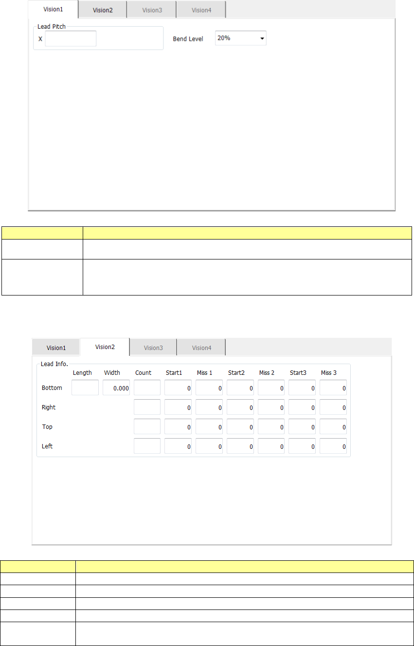
3) QFP, PLCC (QFJ), PQFP (BQFP), J-lead, gull-wing socket and socket with a bumper
The “Vision 1” tab allows you to set the lead pitch and the lead bending level.
Menu item
Overview
Lead Pitch Enter the distance between two consecutive leads.
Bend level
Select the bending level of a lead to be detected among “15 %,”
“20 %,” “25 %,” “30 %” and “None.”
The default value is 20 %.
The “Vision 2” tab allows you to set information on leads located on each side.
Menu item
Overview
Length
Enter the length of a section of a lead that is in contact with a board.
Width
Enter the width of a lead.
Count
Enter the number of leads when a component type is a lead component.
Start 1 to 3
Enter the position of a missing lead.
Miss 1 to 3
Enter the number of missing leads.
The input range is from 0 to the number of leads (default: 0).