RS-1_instruction manual.pdf - 第661页
Pa r t 2 D et ai l ed Des c r i pt i o n of Ea c h F unc t i o n Chapte r 6 G e neral - Purpose Vision Co mpone nt 6- 30 ④ Dimensi on (Point, 1 D or 2 D) For a l ead elem ent , t he dim ension i s one. S elec t “ 1 D. ” …
Part 2 Detailed Description of Each Function Chapter 6 General-Purpose Vision Component
6-29
- The VCS finds each element group of a general-purpose vision component, then
recognizes it with assuming that the component center obtained when you set the
element group layout is on the VCS center.
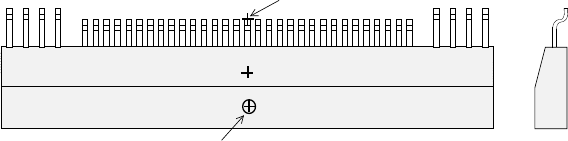
If the component pick-up position is shifted from the center of a component as shown in
the figure, set the following values as the recognition offset: an offset for recognizing a
component so that the center of a component can be located on the VCS center.
Recognition offset X: (Xcenter – Xpick)
Y: (Ycenter – Ypick)
When the machine recognizes a general-purpose vision component, the center for
recognizing a component is the component center obtained when you set the element
group layout.
Therefore, if the placement center position of a component is shifted from the center of a
component as shown in the figure below, set the following values as the Placement
offset: an offset for placing a component so that the placement center point of a
component can be moved on the placement position on a board.
Placement offset X: (Xplace – Xcenter)
Y: (Ycenter – Ycenter)
③
When the first lead end position is set to (- 20.0 mm, - 5.0 mm), set each value in the
“First element position” field as follows:
Offset X : - 20.0
Offset Y : - 5.0
Offset Z : 0 (not used)
Offset Theta: 0
Set “0” to each field of the setting item “Tolerance”.
* Next, set the element group arrangement.
To set the element group arrangement, the setting items “Dimension” (Point, 1D or 2D)",
and “Count” and “Pitch” of the “Column” and “Row” are provided.
Top View
Component center position (Xcenter, Ycenter)
(component outline center)
Component pick-up position (Xpick, Ypick)
Placement center point of a component
Cross
section
Part 2 Detailed Description of Each Function Chapter 6 General-Purpose Vision Component
6-30
④
Dimension (Point, 1D or 2D)
For a lead element, the dimension is one. Select “1D.”
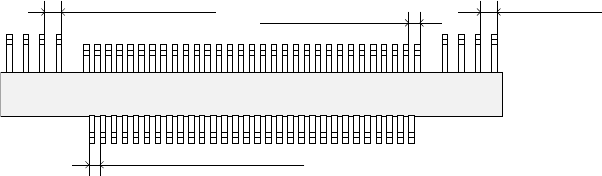
In the example, the number of leads located in the first element group is 30. Enter “30” to
the “Count” field displayed under the setting item “Row.”
The pitch of each element group is shown in the figure.
- When the pitch is 0.5 mm, enter “0.5” in the “Pitch” field.
- Set “0” to the “Tolerance” field.
⑤
Layout inspection
Set the level used for checking the layout of an element group (checking a bent lead of a
lead component). If you are to check the layout, check the “Layout inspection” check box.
In the same manner as setting of a QFP, use the ratio of a bent lead to the lead pitch to set
the bent lead detection level.
- When you want to set the level to “20 %,” check the “Layout inspection” check box, then
check “20 %.”
⑥
Missing Elements
In the example, there is no missing lead on the element group. If there is/are a missing
element(s), specify this setting item also in the same manner as that of a QFP.
Up to four blocks of missing leads can be specified per element group.
To specify a block, set the position of the first missing lead and the number of missing leads
located continuously in the same manner when you set those of a QFP component.
- If three leads are not located from the fifth lead,
Enter “5” to the “Start” field of the “Row” setting item, “3” to the “Count” field.
• Here, you have finished setting an element group. Next, define a recognition element of
this element group
Only one element can be defined per element group. Even though you define two or more
elements, they are handled as “invalid.”
Click the <Add> button in the “Element” setting field.
Top View
Lead pitch of the first element
group
Lead pitch of the
second element group
Lead pitch of the third element
group
Lead pitch of the fourth
element group
Part 2 Detailed Description of Each Function Chapter 6 General-Purpose Vision Component
6-31
3. Operation on the "Element" screen
①
Type
The lead element types are mainly classified into two: inner leads and outer leads.
An inner lead refers to a lead whose end faces toward the inside of a component. An outer
lead refers to a lead whose end faces toward the outside of a component.
- In the example, a component consists of outer leads.
Select “Outer Lead” from the “Type” combo box.
②
Reference pos. (position)
The element origin of a lead element is the lead end as described earlier.
- Select “Center of the bottom” from the “Reference pos.” combo box.
③
Polarity (element polarity)
Specify how bright the image of an element should be.
- Select “Bright” from the “Polarity” combo box because a lead element looks bright under
the reflective light.
④
Offset
Normally, the offset is not used. Set “0” to the “Offset” fields.
⑤
Element size
Enter the element size. In the example, the lead length is 1.0 mm, and the lead width is 0.2
mm. In this case, enter the following values:
Size Width: 0.2
Length: 1.0
Normally, the tolerance is not used. Enter “0” to the “Tolerance” fields.
⑥
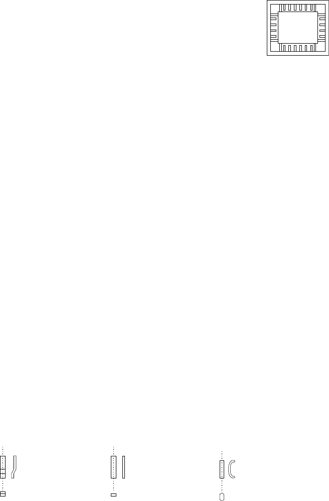
Outer Lead/Inner Lead
□ Profile (lead shape)
As shown in the figure, a lead whose shape is flat entirely is called a “flat lead”, a
stepped lead is called a “gullwing lead”, and a J-shaped lead is called “J-Bend lead.”
♦ A flat lead is often used for a unidirectional connector.
♦ A gullwing lead is often used for a QFP and SOP.
♦ A J-Bend lead is used for a PLCC (QFJ) and SOJ.
- In the example, a gullwing lead is shown.
Select “Gullwing” from the “Profile” combo box.
Example of
inner leads
(of a socket)
Gullwing lead
Flat lead
J-Bend lead