RS-1_instruction manual.pdf - 第732页
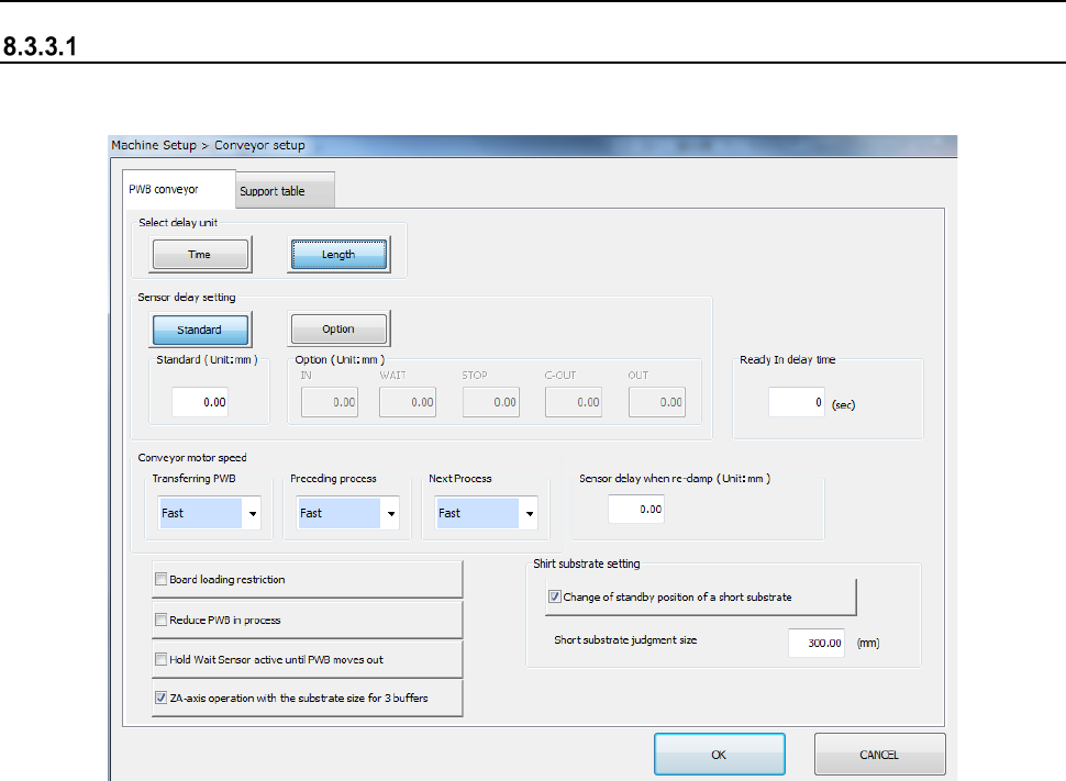
Part 2 D etaile d Descript ion of E ach Functi on Chapter 8 Machine Set up 8- 24 8.3.3 Co n ve yor Conveyor setup When you se lect [Conv eyor setting], the fo llowing s creen appears. W hen yo u c lick each tab, you can …
Part 2 Detailed Description of Each Function Chapter 8 Machine Setup
8-23
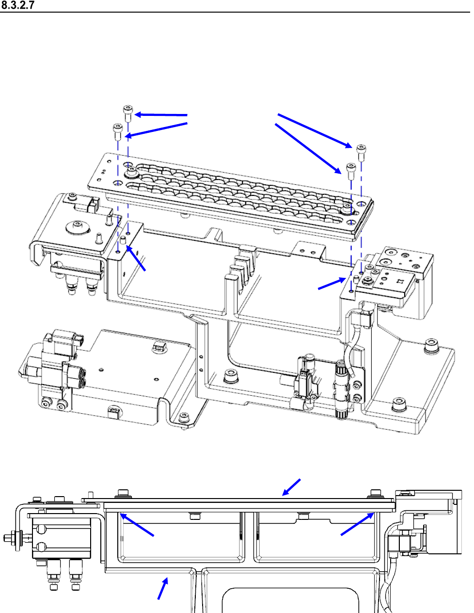
Attaching the R-ATC
To attach the R-ATC on the machine, pay attention to the descriptions below, and then attach it
securely.
(1) Check to see if the reference pins at two positions are positioned to the R-ATC securely.
(2) Check to see if the plate fixing screws (M4 hexagon-socket-head screws) are set at four
positions securely, and the R-ATC adheres to the ATC base.
Reference pin
Reference pin
Plate fixing screws
R-ATC
ATC base
* No gap
* No gap
Part 2 Detailed Description of Each Function Chapter 8 Machine Setup
8-24
8.3.3 Conveyor
Conveyor setup
When you select [Conveyor setting], the following screen appears.
When you click each tab, you can specify “PWB conveyor” or “Support table.”

Part 2 Detailed Description of Each Function Chapter 8 Machine Setup
8-25
(1) Setting item
No.
Item
Description
1
PWB
conveyor
Select delay unit (*)
Sets the units for the delay in the PWB conveyor sensor.
2
Sensor delay setting
(*)
Select standard or option to set the delay time.
3 Standard (*)
Sets the values of delay times or lengths for all the
sensors in cut out and punch hole board conveyance to
the same length.
4 Option (*) Sets the above delay for each sensor separately.
5 Ready In delay time (*)
When the OUT sensor is set to ON to detect a board
while a board is being ejected to the post-process device,
the system checks the status of the ReadyIn signal after
the time set in this “Ready In delay time” field passes.
When the ReadyIn signal is set to ON, the system starts
ejecting a board to the post-process device. The range
of the time you can set in the “Ready In delay time” field
is from 0 to 300 seconds.
6
Conveyor motor speed
(*)
“Transferring PWB” sets the board transportation speed
between the IN sensor and the OUT sensor.
“Preceding Process” sets the speed in which the machine
loads a board from the previous process until it finishes
loading the board into it completely (until the IN sensor is
set to OFF).
“Next Process” sets the board transportation speed
between the OUT sensor and the post-process device.
7
Sensor delay when re-
clamp (*)
Sets the STOP sensor OFF timing during re-clamp.
8
Board loading
restriction
Puts the ReadyOut signal in the OFF status after the final
PWB has been drawn into the transport path of the
machine during production.
9
Reduce PWB in
process
Specify whether to carry in the PWB into a buffer other
than the placement station inside the machine.
10
Hold Wait Sensor
active until PWB
moves out (*)
Specify whether to locate the notch on the WAIT sensor
when the production is stopped by the WAIT sensor.
11
ZA-axis operation with
the substrate size for 3
buffers
Specify whether to adjust the ZA-axis height to the highest
one of the positions at which components have been
already placed in the same manner with 1-buffer mode
when the machine is producing a PWB whose size is
applicable to 3 buffers.
12
Short substrate setting
Set the transport operation of a short-sized board.
13
Change of standby
position of a short
substrate
When the board size is smaller than or equal to the size
set in the “Short substrate judgment size” field, you can
cause the board to wait at the WAIT2 sensor position.
14
Short substrate
judgment size
Specify the board size for determining that the board is
short.
* If a production program makes settings of the conveyor, those settings are applied here.