RS-1_instruction manual.pdf - 第406页
Part 1 B asic O peration Chapter 4 Cr eating a Produc tion Progra m 4- 71 10) Component cue i ng Specify whet her to cue (head) each compon ent and/ or whether to specify a threshold val ue. When a compo nent can be cued…
Part 1 Basic Operation Chapter 4 Creating a Production Program
4-70
6) Speed
Select the speed at which the Z-axis moves when a component is picked up.
When you select load control, the pick descent speed is changed to "FC speed."
7) Auto correct pick
For tape components to be centered with laser, this function corrects a pickup mis-position
automatically based on the recognition result.
The corrected position is entered to the coordinates field of the component pick-up position
on the “Pick” data screen when you select the <Yes> button.
CAUTION
For a component whose center is not picked up, select “No” as the
“Auto correct pick” (select “No” also if you enter the “Picking offset”).
The system corrects the component pick-up position without causing the simultaneous
pick-up to be disordered by correcting the pitch in Y direction when an electric feeder is
used.
8) Auto teaching
This is the function for automatically measuring the center of a component when the system
tracks the component pick-up position.
For square chips 0402 to 3216 whose packaging style is an 8-mm paper tape or 8-mm
emboss tape, you can set [Yes].
However, the default setting is [No] as the auto teaching cannot be performed in accordance
with the color or shape when the packing style is an emboss tape.
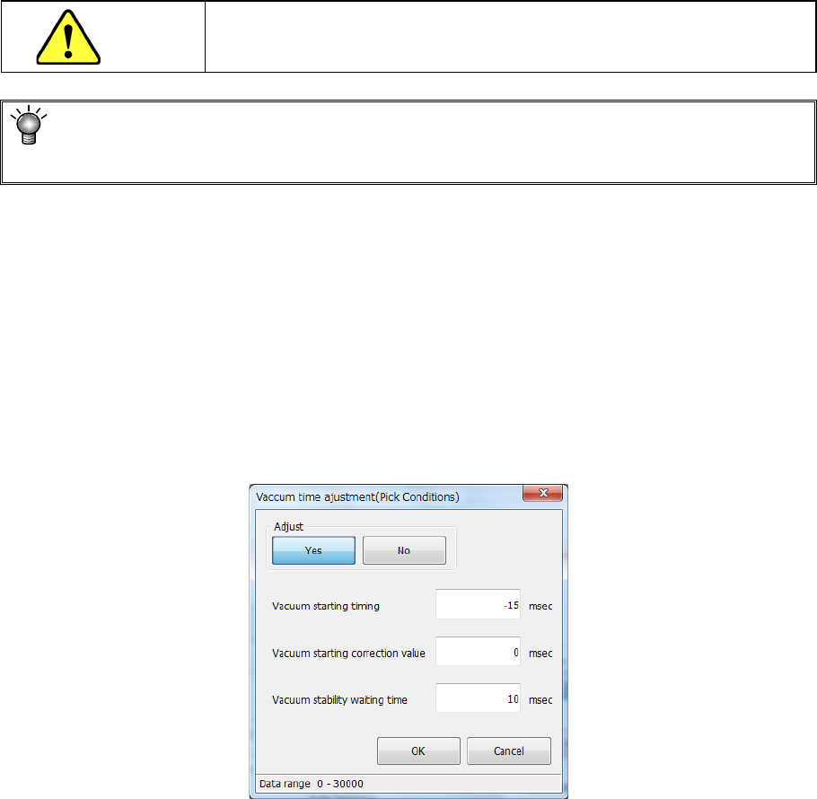
9) Vacuum time adjustment
Specify whether to adjust the vacuum time or not.
When you press the <Setting> button, the following screen appears.
When you select the <Yes> button for the menu item “Adjust,” you can enter an adjustment
value for each item of “Vacuum starting timing,” “Vacuum starting correction value” and
“Vacuum stability waiting time” in milliseconds.

Part 1 Basic Operation Chapter 4 Creating a Production Program
4-71
10) Component cueing
Specify whether to cue (head) each component and/or whether to specify a threshold value.
When a component can be cued, you can specify this menu item, and “Yes” is selected by
default.
Data on a component that can be cued is shown below:
<Cueing of a component with the OCC>
1. 8-mm paper tape or 8-mm embossed tape
2. Component type: Chip (square chip)
3. 0402 to 3216 (0.35 mm ≦ longer side ≦ 3.4 mm, 0.10 mm ≦ shorter side ≦ 1.8
mm)
The menu item “Threshold value” is set to “Not Used” by default.
If a component cannot be cued (headed) with the OCC well, you can specify a threshold
value for detecting existence of a component individually.
Not Used (default)
Select this button if you do not specify a threshold value for detecting
a component to be cued with the OCC individually.
The system operates according to the setting of the main unit.
Used
Select this button if you do not specify a threshold value for detecting
a component to be cued with the OCC individually.
The system operates according to the setting of a production
program.
The default value of the “Threshold value” is 30. You can specify a value in the range of 0
to 40.
11) Control
Specify how to control the stroke to be applied to pick-up of a component.
When a nozzle for controlling low load is selected on the “Centering” tab, the <Low load>
button and the <Load graph> button are enabled on the screen.
When you select the <Low load> button for this menu item, the input unit for the menu item
“Pick stroke” is changed to [g], and the setting of the “Pick Z down” field of the menu item
“Speed” is changed to “FC speed.”
When you press the <Load graph> button, you can check the pressure that can be applied
with the nozzle.
Part 1 Basic Operation Chapter 4 Creating a Production Program
4-72
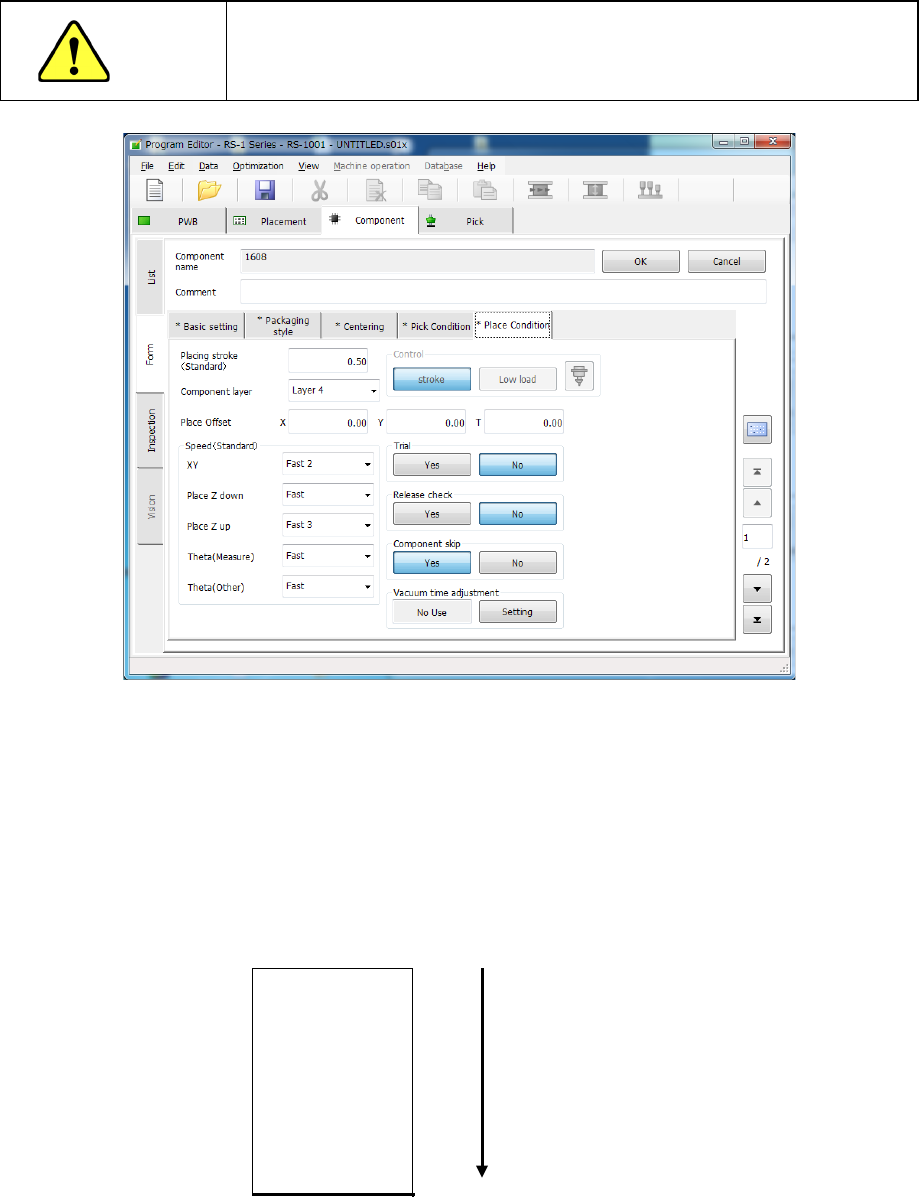
(5) Place Condition
The placement conditions consist of setting items related to placement and default values
are applied. Accordingly, they do not need to be changed. If placement cannot be
performed normally in the default value status, change the settings. Note that if you change
the setting(s) of the “Basic setting” tab sheet after changing the settings of the “Place
Condition” tab sheet, settings of some menu items are reset to the default ones.
CAUTION
If you change any of the basic settings after changing any value on the
“Place Condition” tab, some values are reset to their defaults on the
“Place Condition” tab.
1) Placing stroke
Specify how much to push the tip of a nozzle when a component is placed on a board.
2) Component layer
The “Component layer” field specifies the priority of each component on the same
placement layer.
This selection is effective only if the system produces a PWB in the optimized order.
Note that since this setting is for the priority of the optimized placement order, this does not
specify the placement order strictly, so that this does not put the machine into the pause
state when components run out unlike the placement layer.
Select the layers from 1 (highest priority) to 7 (lowest priority) from the pull-down list.
Layer 1
Layer 2
Layer 3
Layer 4
Layer 5
Layer 6
Layer 7
Place first.
Place later.