RS-1_instruction manual.pdf - 第1042页
Pa r t 2 D et ail ed Des c r i p ti on of Each Function C hapter 1 3 Supp l em en t ar y I nf o rm ati on f or C r eating a Production P rogra m 13 - 19 Patt ern s wh ich can be reg ist er ed as th e use r de fin ed tem …
Part 2 Detailed Description of Each Function Chapter 13 Supplementary Information for
Creating a Production Program
13-18
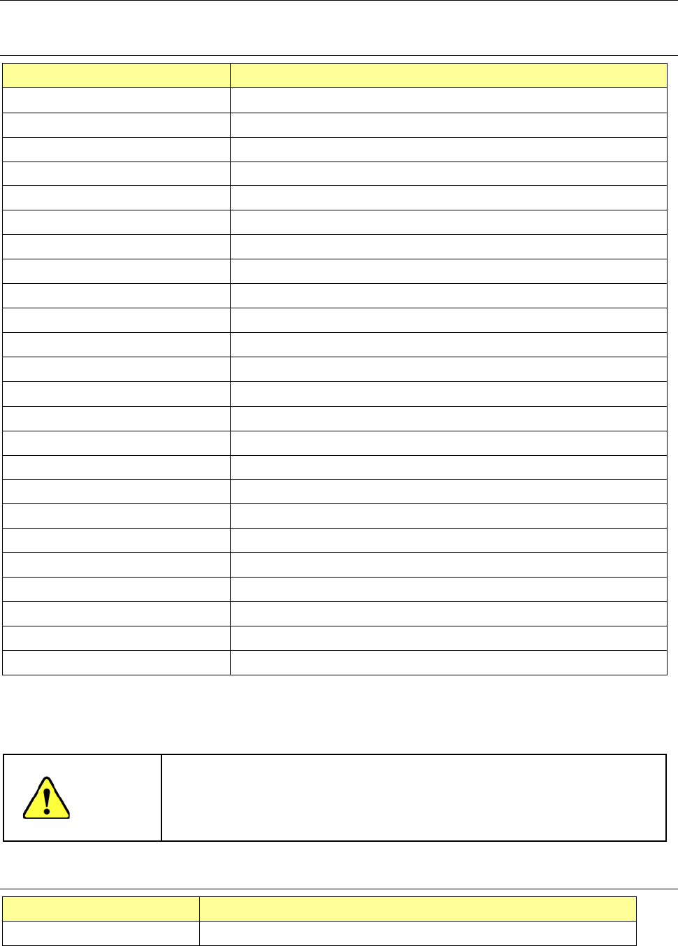
File type of Production Programs 13.4
Read enable file type table 13.4.1
Type name (extension) Explanation of program file
RS-1/1R type file (s01x) File created by RS-1/1R main unit
RX-7 type file (prd) File created by RX-7 main unit
RX-6/6B/6R type file (j01x) File created by RX-6
2050/2050R type file (e54) File created by 2050/2050R main unit
2060 type file (e46) File created by 2060 main unit
2070 type file (e47) File created by 2070/1070 main unit
2080 type file (e48) File created by 2080/2080R main unit
CX-1 type file (e56) File created by CX-1 main unit
FX-1/FX-1R type file (e51) File created by FX-1/FX1R main unit
FX-2 type file (X52) File created by FX-2 main unit
FX-3 type file (x01) File created by FX-3 main unit
2077 type file (X52) File created by FX-2 main unit
3010 type file (X11) File created by 3010 main unit
3020 type file (x21) File created by 3020/3020R
File divided by optimization (i01) File divided for machine #1 of line by Production support system
File divided by optimization (i02) File divided for machine #2 of line by Production support system
File divided by optimization (i03) File divided for machine #3 of line by Production support system
File divided by optimization (i04) File divided for machine #4 of line by Production support system
File divided by optimization (i05) File divided for machine #5 of line by Production support system
File divided by optimization (i06) File divided for machine #6 of line by Production support system
File divided by optimization (i07) File divided for machine #7 of line by Production support system
File divided by optimization (i08) File divided for machine #8 of line by Production support system
File divided by optimization (i09) File divided for machine #9 of line by Production support system
File divided by optimization (i10) File divided for machine #10 of line by Production support system
* The extension may be the same in the production program created by the mounter not listed in the
above "Explanation of program file", but please do not read it because RS-1/1R does not support it.
Example: JX 300 LED is the same as 2070 format file (e 47)
CAUTION
* Precautions on reading data
The 770, 775, 2077, RX-7 type file contains component names but no
contents of component data. For the files of a type other than RS-1/1R,
the pick data is selected automatically.
Save enable file type table 13.4.2
Type name (extension) Explanation of program file
RS-1/1R type file (s01x) File created by RS-1/1R

Part 2 Detailed Description of Each Function Chapter 13 Supplementary Information for
Creating a Production Program
13-19
Patterns which can be registered as the user defined template 13.5
1) Patterns which can be registered as the user defined template
1) Wiring pattern
2) Pad and land pattern where no screen is printed (no solder paste is put)
3) PWB marks other than JUKI standard marks (whole or part)
2) Notes on registration as the user defined template
Through hole and pier hole
Since the pattern generation process is different from the holing process, the same
positioning cannot be always achieved. (The hole position is undefined for a pattern.)
To register the template based on the through hole or pier hole, include the wiring pattern
around the hole.
3) Pattern which cannot be registered as the user defined template
1) Silk (character) pattern
Since the pattern and pad generation process is totally different from the silk printing
process, the placement position cannot be determined based on the silk print.
2) Pad and land pattern printed on the silk screen
The solder paste on the screen is in the form of grains, so lighting cannot be stable
depending on the environment or condition. The template matching is highly appropriate
for change of lighting conditions, but not for the change of polarity (positive and negative).
3) The similar pattern is located on the same recognition screen
4) The template whose difference between the brightness and the darkness is little.
5) Pattern whose scale (size) and/or angle changes
Especially if a part of the pattern is specified as the user defined template, change of the
scale affects the recognition accuracy. Therefore, specify the entire pattern as the user
defined template if possible.
The farther the gravity center of the template (as described above) is from the that of the
template, the more the angle change affects the recognition operation: the recognition
position is shifted. Set the user defined template so that the gravity center of the
template matches with the center of the template as correctly as possible.
When you press the camera button, white and black can be reversed. Accordingly, if the
mark is imaged in black for PWB, press the camera button to reverse while and black so
that the mark may be imaged in white. The mark reverse by the camera button is
enabled only when the scale frame is input.

Part 2 Detailed Description of Each Function Chapter 13 Supplementary Information for
Creating a Production Program
13-20
Laser status list 13.6
- Shown below is the list of status that is returned from laser when it obtains the result of your
clicking of the <Meas. (ONCE)> or <Meas. (SWEEP)> push button as the “Control item” on
the “Laser control” dialog box.
Status
Description
0 Indicates that the command was finished.
1 Indicates that the command was normally executed.
11 Indicates that the left-end window is covered. Check he component position.
12 Indicates that the right-end window is covered. Check he component position.
13 Indicates that both-end windows are covered. Check the component position.
20 An error occurred in communication with LNC120.
21 The communication with LNC120 could not be established successfully. Check whether LNC120 is correctly
connected. (The IP address may not set correctly.)
22 A component can always be detected on the laser. The nozzle may be too long or the laser surface may be
damaged.
23 No component can be detected by lowering the Z-axis.
25 An error occurred in axis movement during laser measurement.
26 An error occurred in communication with the laser sensor but the communication was restored.
27 An error occurred in communication with the laser sensor. The communication could not be restored.
Restart the machine.
28 No shadow could be detected during measurement.
30 An illegal parameter was detected in the command.
31 Illegal data was detected.
32 Laser recognition could not be completed.
33 Measurement resulted in an error for other reason.
34 The encoder input error. Check the encoder cable and connector for contact.
40 In the data received from the laser, a packet number error was detected.
41 In the data received from the laser, a command error was detected.
42 In the data received from the laser, an address error was detected.
43 In the data received from the laser, a data number error was detected.
44 In establishing communication with the laser, a timeout error occurred.
45 In receiving data from the laser, a timeout error occurred.
46 In sending data to the laser, a timeout error occurred.
47 In sending data to the laser, a retry-over occurred.
50 In ONCE recognition processing, a recognition error occurred.
51 A sensor error was detected during ONCE recognition processing.
60 Though measurement was not executed, a request to obtain a measurement result was executed.
61 No measurement data could be obtained.
62 A request to obtain a measurement result was executed during measurement rotation.
63 A request to obtain a measurement result was executed during measurement rotation.
64 Correct data for measurement could not be obtained.
65 Measurement cannot be performed because the center of rotation of the object to be measured is out of the
center of measurement.
66 Now, measurement is interrupted.
67 Enough data for measurement could not be obtained.
68 A request to obtain a measurement result was executed during measurement rotation. (During door angle)
70 The sensor was executed unless the laser was initialized.
71 An unexpected error occurred in the laser.
72 Measuring processing cannot be executed because the set window size is small.