RS-1_instruction manual.pdf - 第664页
Pa r t 2 D et ai l ed Des c r i pt i o n of Ea c h F unc t i o n Chapte r 6 G e neral - Purpose Vision Co mpone nt 6- 33 W hen you h av e the n ext el em ent g r oup to b e defi ned at t hi s p oint, cl ick the < Ad…

Part 2 Detailed Description of Each Function Chapter 6 General-Purpose Vision Component
6-32
⑦
Cut shape
Specify the shape of a lead end.
All of the settings other than “Flat” are handled in the same manner. When you select a
setting other than “Flat”, set the “Cut width” and “Cut length” fields.
- In the example, the shape of a lead end is flat.
Select “Flat” from the “Cut shape” combo box.
⑧
Coating
This item is not to be used. Select “Bare” from this combo box.
⑨
Cut width
This item is not to be used. Enter “0” to this field.
⑩
Cut length
Set this item if you select a setting other than “Flat” from the “Cut shape” combo box.
Enter the length of a not-flat portion measured from the lead end.
- In the example, the shape of a lead end is flat.
Enter “0” to the “Cut length” field.
⑪
Lead size
For a gullwing lead, enter the lead foot size here.
The “lead foot size” indicates the portion of a gullwing lead which is in contact with a board.
- In the example, the length of a gullwing lead foot is 0.5 mm.
Enter the following values:
Width : 0.2 (same as the lead width)
Length : 0.4
●
Here, you have finished entering element data. When you click the <OK> button
displayed on the lower right corner, the “Element Group” screen reappears.
● You have finished defining the first element group. When you click the <OK> button
displayed on the lower right corner, the “Element Data” screen reappears.
Part 2 Detailed Description of Each Function Chapter 6 General-Purpose Vision Component
6-33
When you have the next element group to be defined at this point, click the <Add> button to
define the element group by entering data in the same manner.
In the example, there are four element groups. Define four element groups.
All data to be entered is shown below:
Element
group
name
First element
position
Layout
inspection
(Dimension)
Missing
elements
Element
Element
offset
Element size
Element
shape
Cutting Lead size
ELG0001
X:-7.25
Y: -5.1
Z: 0
θ: 0
Tolerance:
All set to 0.
√ 25%
√ ID
Count of
Column: 30
Pitch of
Column: 0.5
Tolerance: 0
Start: 5
Count: 3
Type:
Outer Lead
Reference pos.:
Center of the
bottom
Polarity: Bright
Offset:
all set to 0.
Tolerance:
all set to 0.
Size
X: 0.2
Y: 1.0
Tolerance:
all set to 0.
Profile:
Gullwing
Cut shape:
Flat
Coating:
Bare
Cut width: 0
Cut length: 0
Size
X: 0.2
Y: 0.4
Tolerance:
all set to 0.
ELG0002 X: 13.31
Y: 5.1
Z: 0
θ: 180
Tolerance:
All set to 0.
√ 25% √ ID
Count of
Column: 4
Pitch of
Column:
1.27
Tolerance: 0
Type:
Outer Lead
Reference pos.:
Center of the
bottom
Polarity: Bright
Offset:
all set to 0.
Tolerance:
all set to 0.
Size
X: 0.4
Y: 1.2
Tolerance:
all set to 0.
Profile:
Gullwing
Cut shape:
Flat
Coating:
Bare
Cut width: 0
Cut length: 0
Size
X: 0.4
Y: 0.6
Tolerance:
all set to 0.
ELG0003
X: 7.5
Y: 4.9
Z: 0
θ: 180
Tolerance:
All set to 0.
√ 25%
√ ID
Count of
Column: 31
Pitch of
Column: 0.5
Tolerance: 0
Type:
Outer Lead
Reference pos.:
Center of the
bottom
Polarity: Bright
Offset:
all set to 0.
Tolerance:
all set to 0.
Size
X: 0.2
Y: 1.0
Tolerance:
all set to 0.
Profile:
Gullwing
Cut shape:
Flat
Coating:
Bare
Cut width: 0
Cut length: 0
Size
X: 0.2
Y: 0.4
Tolerance:
all set to 0.
ELG0004 X: -9.5
Y: 5.1
Z: 0
θ: 180
Tolerance:
All set to 0.
√ 25% √ ID
Count of
Column: 4
Pitch of
Column:
1.27
Tolerance: 0
Type:
Outer Lead
Reference pos.:
Center of the
bottom
Polarity: Bright
Offset:
all set to 0.
Tolerance:
all set to 0.
Size
X: 0.4
Y: 1.2
Tolerance:
all set to 0.
Profile:
Gullwing
Cut shape:
Flat
Coating:
Bare
Cut width: 0
Cut length: 0
Size
X: 0.4
Y: 0.6
Tolerance:
all set to 0.
Click the <OK> button at the lower left corner of the screen after you define all element groups to
finish the “Element Data” data entry.
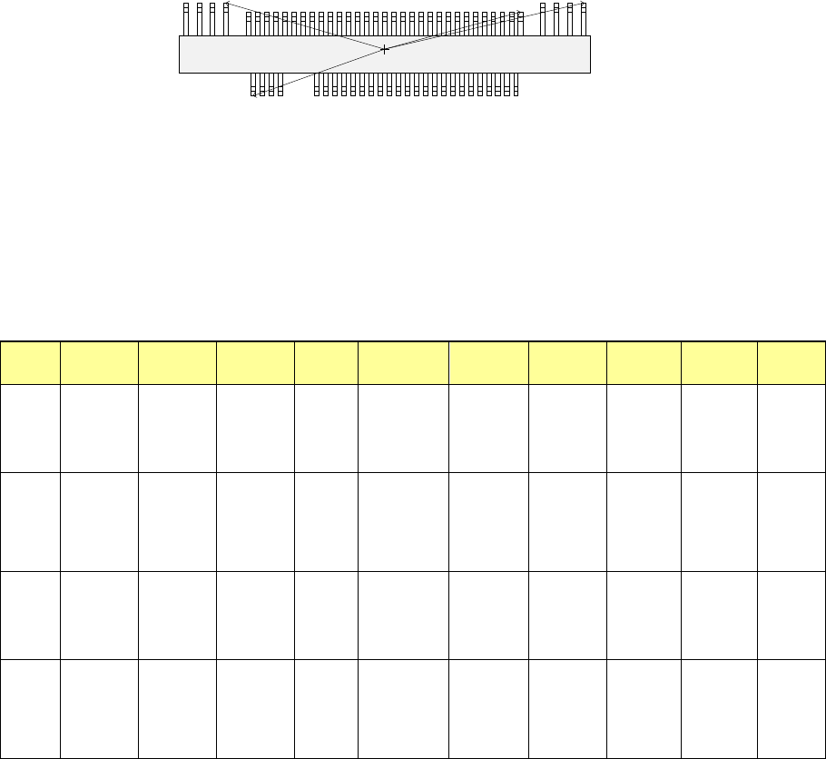
Top View
Forth element group
(X, Y): (- 9.50, 5.1) mm
Theta: 180 degrees
Pitch: 0.5 mm,
Count: 4
Lead length: 1.2 mm
Lead width: 0.4 mm
Gullwing lead: Flat
Foot length: 0.6 mm
Foot width: 0.4 mm
Third element group
(X, Y): (7.5, 4.9) mm
Theta: 180 degrees
Pitch: 0.5 mm
Count: 31
Lead length: 1.0 mm
Lead width: 0.2 mm
Gullwing lead: Flat
Foot length: 0.4 mm
Foot width: 0.2 mm
Second element group
(X, Y): (13.31, 5.1) mm
Theta: 180 degrees
Pitch: 1.27 mm
Count: 4
Lead length: 1.2 mm
Lead width: 0.4 mm
Gullwing lead: Flat
Foot length: 0.6 mm
Foot width: 0.4 mm
First element group
(X, Y): (- 7.25, - 5.1) mm
Theta: 0 degrees
Pitch: 0.5 mm
Count: 30
Missing leads: three from the fifth lead
Lead length: 1.0 mm
Lead width: 0.2 mm
Gullwing lead: Flat
Foot length: 0.4 mm
Foot width: 0.2 mm
Part 2 Detailed Description of Each Function Chapter 6 General-Purpose Vision Component
6-34
Ball components (Element group/Element format) 6.5.2
This section describes the procedure for creating data on ball components (complex array
components).
1. Operation on the “Element Data” screen
- Select “Ball Component” from the “Component Type” combo box.
- Check the “Element group/Element format” check box in the “Define data format” field.
- Click the <Add> button on the “Element Group List.”
2. Operation on the “Element Group” screen
Define an element group.
An element group consists of components whose size and pitch is the same as each other.
A complex array component refers to an area array component whose size is different or
whose ball/land pitch is different from each other.
When the lead pitch is not the same even though the polarity is the same, set element
groups separately. If the polarity is the same, the size and shape of the polarity is the same
also.
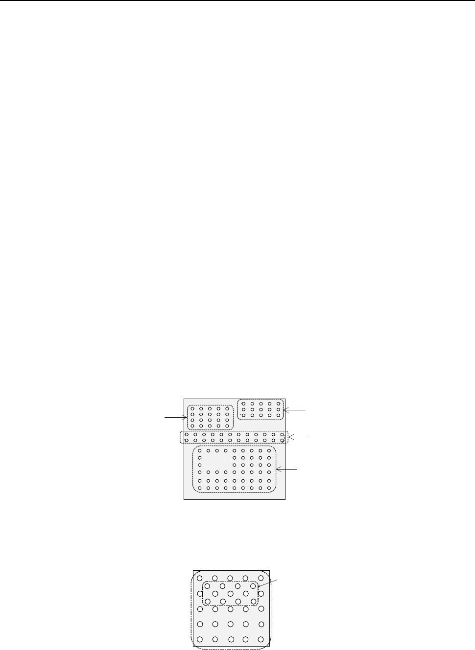
In the example shown a complex array component that consists of four element groups is
shown.
◆ Description
The procedure for creating data on this component is to be described below.
The element size and pitch of the second and third element groups are the same as each
another. However, columns of elements are not aligned with each another. Define them as
two different element groups.
The posture of a complex array component is viewed from the bottom in the same manner as
an area array component such as a BGA and FBGA.
When a component has a staggered pattern of elements partially as shown in the figure, divide
them into two grid arrangement groups, then define them.
Bottom View
Third element group
Fourth element group
Second element group
First element group
Element group 1
Element group 2