RS-1_instruction manual.pdf - 第976页
Part 2 D etaile d Descript ion of E ach Functi on Chapter 12 Handling th e Optional Device s 12 - 92 ◆ C opla narity of a lead c omponent obtai ned with the 3 - point m ethod (defa ult) In t he geometric pla ne passing t…
Part 2 Detailed Description of Each Function Chapter 12 Handling the Optional Devices
12-91
12.14.2 Items to be inspected with a coplanarity check
12.14.2.1 Colinearity check
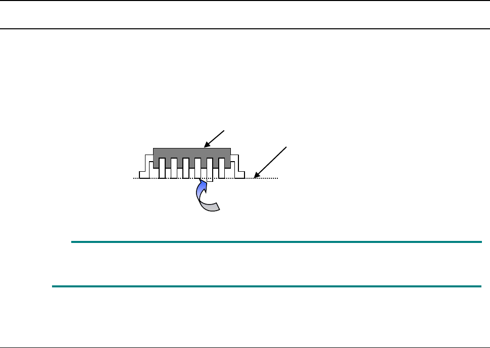
This check inspects whether a side on which a lead is located is “bent upwards or downwards.”
◇ This check is run with “one scanning operation.” For example, each of “four sides of a 4-side
element such as a QFP” or each of “two sides of a 2-side element such as an SOP” is
inspected with one scanning operation.
“Colinearity” means parallelism.
A colinearity check can be run for a lead component only.
12.14.2.2 Coplanarity check
To calculate coplanarity, two methods are provided:
Coplanarity (uniformity of the bottom of a terminal) of a QFP/SOP can be calculated with the 3-point
method (JEDEC standard: JESD22-B108A) or the least-square method (JEDEC standard:
JESD22-B108A).
■ The 3-point method is selected at the factory.
This setting can be changed on the “Machine Setup” screen (See Section 8.3.6.8
“Coplanarity”).
◇ Coplanarity of a QFP or an SOP can be calculated with the 3-point method or the least-square
method.
◇ Coplanarity of a ball component can be calculated with the least-square method.
Measurement line
This lead is bent downwards
Element to be checked
Part 2 Detailed Description of Each Function Chapter 12 Handling the Optional Devices
12-92
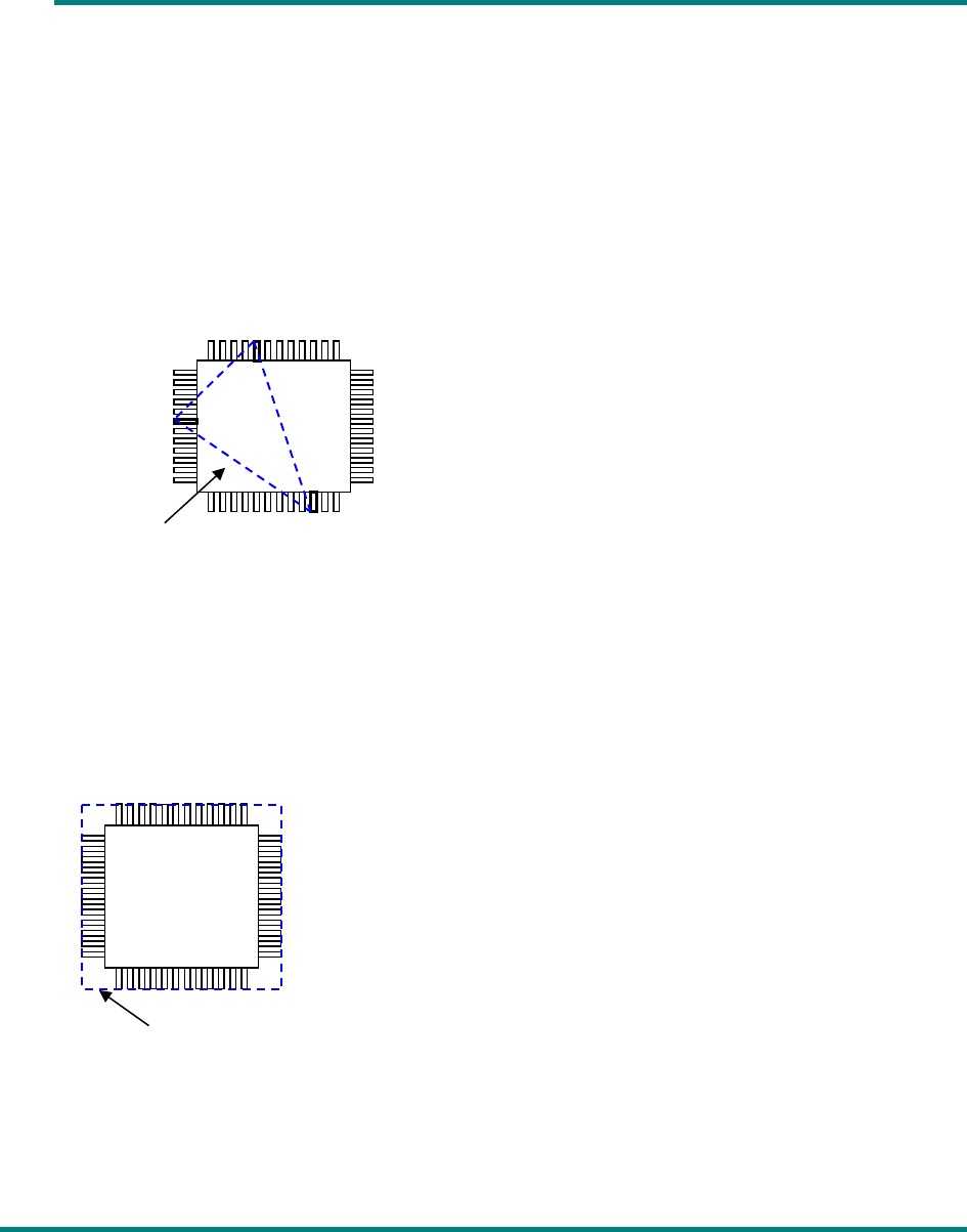
◆ Coplanarity of a lead component obtained with the 3-point method (default)
In the geometric plane passing the lowest points of arbitrary three terminals, all the lowest
points of the other terminals exist on the package side and the center of gravity of the
package is included within or on sides of the triangle comprised of these three points. When
the plane satisfies the above condition and has no effect of the empty weight, it is defined as
coplanarity.
If there are multiple combinations that satisfy the above condition, adopt a combination in
which the coplanarity value becomes large.
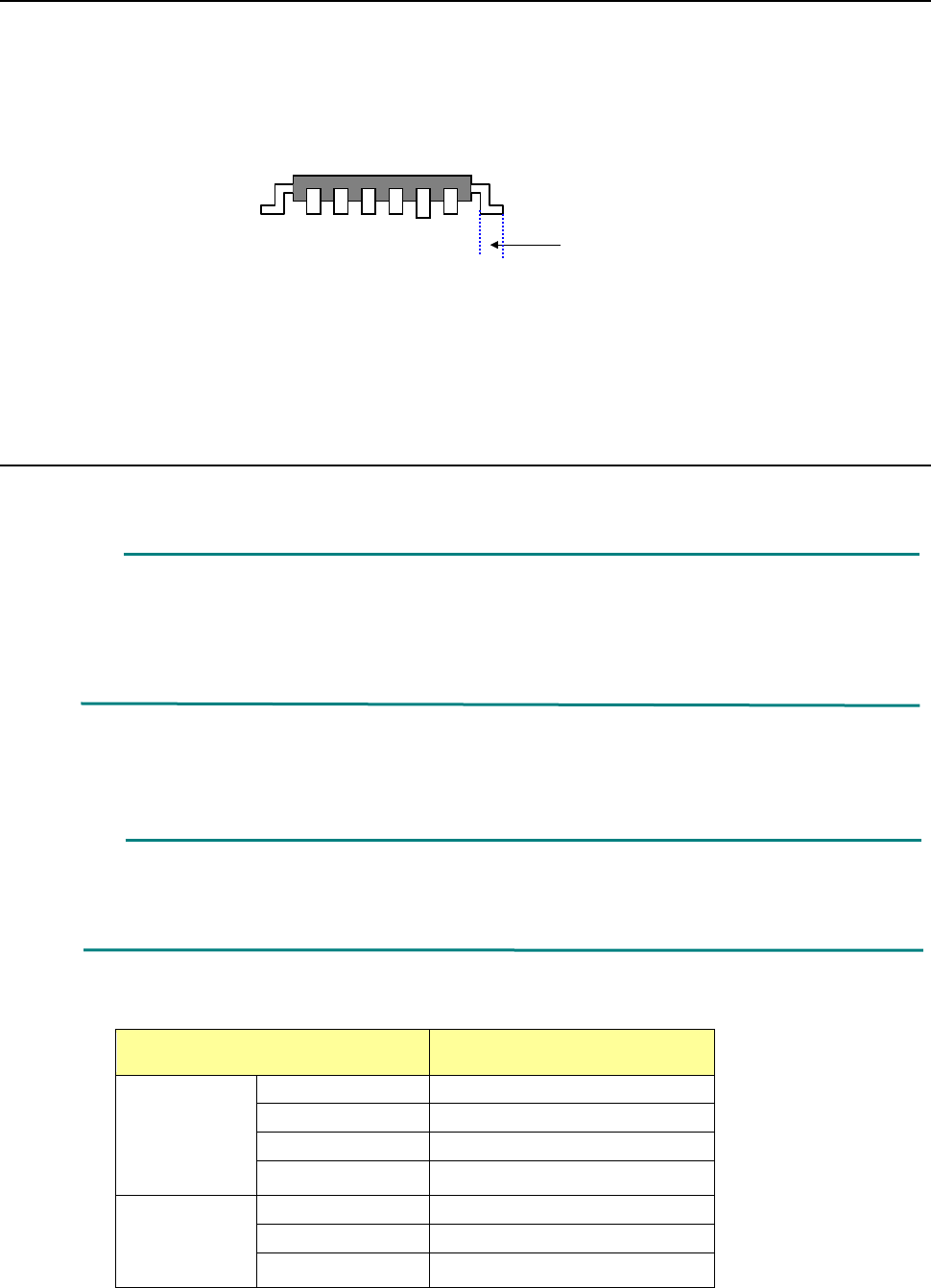
◆ Coplanarity of a lead component obtained with the least-square method
In case of the least-square method, when the plane obtained by the least-square method from
the lowest points of all the terminals is in contact with the lowest point of the most distant
terminal from the package side, the distance up to the most distant terminal is defined as
coplanarity.
◆ Coplanarity of a ball component obtained with the least-square method
When the plane obtained by the least-square method from the vertexes of all balls is in
contact with the vertex of the most distant ball from the package side, the distance up to the
most distant ball is defined as coplanarity.
Plane obtained with the lowest points
Plane obtained with the least-square method
Part 2 Detailed Description of Each Function Chapter 12 Handling the Optional Devices
12-93
12.14.2.3 Criteria for a check
■ Colinearity check (available for a lead component only)
The machine uses a value set in the “Tolerance” field of the “Coplanarity check” on the
“Component” data screen invoked with the Program Editor to check upward/downward
bending of leads on each side.
◇ A position to be checked is the center of the side of a board on which each lead is set.
■ Coplanarity check
The machine uses a value set in the “Tolerance” field of the “Coplanarity check” on the
“Component” data screen invoked with the Program Editor to check upward/downward
bending of leads.
12.14.3 Overview of the specifications
(1) Applicable components
QFP, SOP, BGA and connector
* These components are applicable only if they are recognized with a VCS.
For a ball component (BGA), the machine measures only a ball component whose
“Contrast” is set to “All balls-PWB” or “All balls-Ceramic” on the “Vision 1” tab. Note that a
component whose data is created as a general-purpose vision component is not
applicable.
(2) Resolution and precision
① Resolution: 1μm
② Precision (3σ) : ± 15 μm
This unit may not correctly judge a component whose terminal is damaged due to contact
with a contact probe. It may not be able to correctly judge a lead component whose
terminal is not rectangle-shaped or whose side to be measured is not flat either.
(3) Component dimensions
Item Dimensions
Lead
component
Pitch
0.4 mm or more
Lead width
0.2 mm or more
Lead length
0.3 mm or more
Component size
48 mm x 150 mm or less
Ball
component
Pitch
0.8 mm or more
Ball diameter
0.4 mm or more
Component size
48 mm x 150 mm or less
Scanning position